Suzuki Grand Vitara JB416 / JB420 / JB419. Manual - part 251
 

  Index      Suzuki     Suzuki Grand Vitara JB416 / JB420 / JB419 - service repair manual 2007 year


Search            


Content   ..  249  250  251  252   ..


Suzuki Grand Vitara JB416 / JB420 / JB419. Manual - part 251


3C-35 Transfer: Motor-Shift Type (Transfer with Shift Actuator)

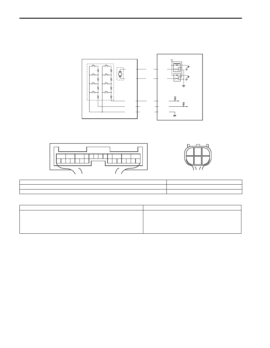
DTC C1224 / C1236: Transfer Shift Actuator Motor Position Switch 1 Circuit Short / Transfer Shift 
Actuator Motor Position Switch 2 Circuit Short

S6JB0A3314017

Wiring Diagram

DTC Detecting Condition and Trouble Area

DTC Confirmation Procedure

1) Clear DTC using scan tool.
2) Select transfer switch to “4H” position and keep its position for 10 seconds. Similarly select transfer switch to “4H-

lock”, “N” and “4L-lock” position.

3) Check DTC.

5V

12V

E91-2

5V

YEL

RED/BLK

BLU

M

E91-3

E91-25

E91-26

RED

E91-24

BLK/YEL

1

2

3

C54-1

C54-4

C54-2

C54-3

C54-5

4

1

2

3

4

5

6

7

8

9

10

11

12

13

14

15

16

17

18

19

20

21

22

23

24

25

26

[A]

1

2

3

4

5

6

[B]

I5JB0A332017-01

[A]: 4WD control module connector “E91” (viewed from harness side)

2. Transfer shift actuator motor position switch

[B]: Transfer shift actuator connector “C54” (engine harness side) (viewed from harness side)

3. Transfer shift actuator motor

1. Transfer shift actuator

4. 4WD control module

DTC detecting condition

Trouble area

Transfer shift actuator motor position switch signal voltage 0.6 V 
or less.

• Transfer shift actuator motor position switch
• Transfer shift actuator motor position switch 

circuit

• 4WD control module

Transfer: Motor-Shift Type (Transfer with Shift Actuator) 3C-36

Troubleshooting

Step

Action

Yes

No

1

Was “4WD control system check” performed?

Go to Step 2.

Go to “4WD Control 
System Check: Motor-
Shift Type (Transfer with 
Shift Actuator)”.

2

Transfer shift actuator motor position switch circuit 
check
1) Disconnect transfer shift actuator connector “C54” with 

ignition switch OFF.

2) Check for proper connection to “C54-2”, “C54-3” and 

“C54-5” terminals of transfer shift actuator connector.

3) If connection is OK, measure voltage between “G54-2”, 

“G54-3” or “G54-5” terminal of transfer switch connector 
and vehicle body ground with ignition switch ON.

Is it approx. 5 V?

Go to Step 3.

Go to Step 4.

3

Transfer shift actuator position switch check
1) Check transfer shift actuator position switch referring to 

“Transfer Assembly Inspection: Motor-Shift Type 
(Transfer with Shift Actuator)”.

Is actuator in good condition?

Substitute a known-
good 4WD control 
module and recheck.

Faulty actuator position 
switch. Replace transfer 
shift actuator.

4

Wire harness check
1)  Disconnect connector from 4WD control module 

connector “E91” with ignition switch OFF.

2) Check for shorted to ground in related circuits.

• Between “C54-2” terminal of transfer shift actuator 

connector and “E91-25” terminal of 4WD control 
module connector

• Between “C54-3” terminal of transfer shift actuator 

connector and “E91-26” terminal of 4WD control 
module connector

• Between “C54-5” terminal of transfer shift actuator 

connector and “E91-24” terminal of 4WD control 
module connector

Are they in good condition?

Substitute a known-
good 4WD control 
module and recheck.

Repair circuit.

3C-37 Transfer: Motor-Shift Type (Transfer with Shift Actuator)

DTC C1227: 4L/N Switch Circuit Open

S6JB0A3314018

Wiring Diagram

DTC Detecting Condition and Trouble Area

DTC Confirmation Procedure

1) Clear DTC using scan tool.
2) Select transfer switch to “4L-lock” position and keep its position for 1 min.
3) Check DTC.

Troubleshooting

IG

E91-13

E91-14

RED/GRN

PNK/WHT

2

3

4

12V

1

1

2

3

4

5

6

7

8

9

10

11

12

13

14

15

16

17

18

19

20

21

22

23

24

25

26

[A]

I5JB0A332018-01

[A]: 4WD control module connector “E91” (viewed from harness side)

3. 4L/N switch

1. 4WD control module

4. Center differential lock switch

2. TCM

DTC detecting condition

Trouble area

Though transfer shift actuator motor position switch is “4L-lock” 
position, the ON signal is not input from the 4L/N switch.

• 4L/N switch
• 4L/N switch circuit
• 4WD control module

Step

Action

Yes

No

1

Was “4WD control system check” performed?

Go to Step 2.

Go to “4WD Control 
System Check: Motor-
Shift Type (Transfer with 
Shift Actuator)”.

2

4L/N switch circuit check
1) Disconnect 4L/N switch connector with ignition switch 

OFF.

2) Check for proper connection to terminal of 4L/N switch 

connector.

3) If connection is OK, measure voltage between “PNK/

WHT” terminal of 4L/N switch connector and vehicle 
body ground with ignition switch ON.

Is it 10 – 14 V?

Go to Step 3.

Go to Step 4.

Transfer: Motor-Shift Type (Transfer with Shift Actuator) 3C-38

DTC C1228: 4L/N Switch Circuit Short

S6JB0A3314019

Wiring Diagram

DTC Detecting Condition and Trouble Area

DTC Confirmation Procedure

1) Clear DTC using scan tool.
2) Select transfer switch to “4L-lock” position and keep its position for 1 min.
3) Check DTC.

3

4L/N switch check
1) Check 4L/N switch referring to “Transfer Assembly 

Inspection: Motor-Shift Type (Transfer with Shift 
Actuator)”.

Is switch in good condition?

Substitute a known-
good 4WD control 
module and recheck.

Replace 4L/N switch.

4

Wire harness check
1) Disconnect connector from 4WD control module 

connector “E91” with ignition switch OFF.

2) Check for proper connection to “E91-13” terminal of 

4WD control module connector.

3) If OK, measure resistance between “PNK/WHT” terminal 

of 4L/N switch connector and “E91-13” terminal of 4WD 
control module connector.

Is it 1 

 or less?

Substitute a known-
good 4WD control 
module and recheck.

“PNK/WHT” wire is 
open or high resistance.

Step

Action

Yes

No

IG

E91-13

E91-14

RED/GRN

PNK/WHT

2

3

4

12V

1

1

2

3

4

5

6

7

8

9

10

11

12

13

14

15

16

17

18

19

20

21

22

23

24

25

26

[A]

I5JB0A332018-01

[A]: 4WD control module connector “E91” (viewed from harness side)

3. 4L/N switch

1. 4WD control module

4. Center differential lock switch

2. TCM

DTC detecting condition

Trouble area

Though transfer shift actuator motor position switch is “4L-lock” 
position, the OFF signal is not input from the 4L/N switch.

• 4L/N switch
• 4L/N switch circuit
• 4WD control module


Content   ..  249  250  251  252   ..