Suzuki Grand Vitara JB416 / JB420 / JB419. Manual - part 238
 

  Index      Suzuki     Suzuki Grand Vitara JB416 / JB420 / JB419 - service repair manual 2007 year


Search            


Content   ..  236  237  238  239   ..


Suzuki Grand Vitara JB416 / JB420 / JB419. Manual - part 238


3B-23 Differential: Rear

b. Support rear differential with transmission 

jack.

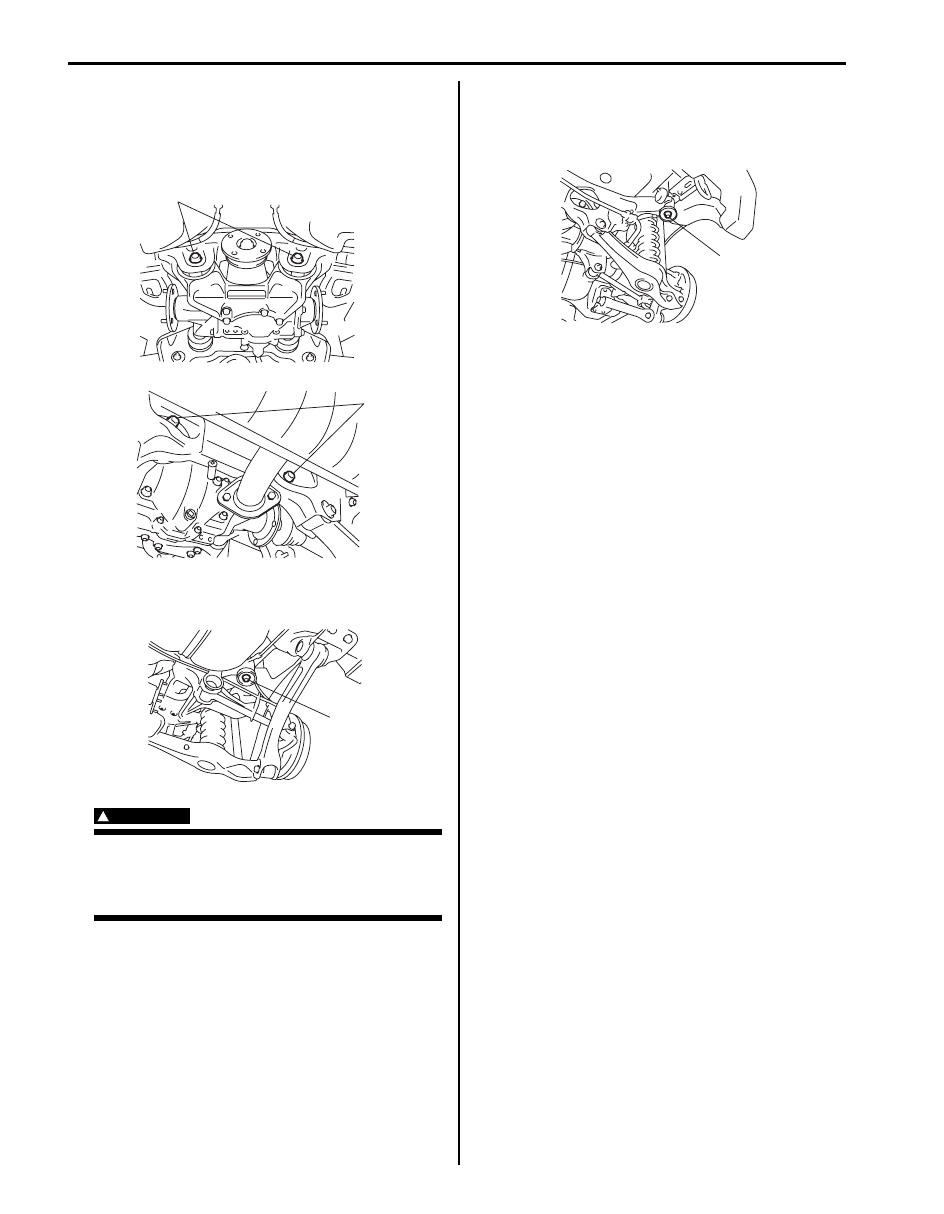
c. Loosen rear differential mounting front bolts 

(1) and rear bolts (2).
Do not remove them in this step.

d. Remove rear suspension frame mount front 

bolts (1).

WARNING

!


Do not loosen rear suspension frame rear 
bolts more than 8 turns. Otherwise, rear 
suspension frame may fall and cause 
personal injury.


e. Loosen rear suspension frame mount rear 

bolts gradually within 8 turns until rear 
differential mounting front bolts can be 
removed.

f.

Remove rear differential mounting front and 
rear mounting bolts, and then lower rear 
differential.

g. Tighten temporarily rear suspension frame 

mount front and rear bolts.

• 5 door model

a. Support rear differential with transmission 

jack.

b. Remove front and rear mounting bolts, and 

then lower rear differential.

Remounting
Reverse dismounting procedure for remounting noting 
the following.
• Tighten rear differential mounting front and rear bolts 

to specified torque.

Tightening torque
Rear differential front mounting bolt:  120 N·m (
12.0 kgf-m, 87.0 lb-ft)
Rear differential rear mounting bolt:  120 N·m (
12.0 kgf-m, 87.0 lb-ft)

• Tighten rear suspension frame front and rear bolts to 

specified torque referring to “Rear Suspension 
Construction in Section 2C”
.

• Fill rear differential oil referring to “Rear Differential Oil 

Change: Rear”.

1

2

I5JB0A322003-01

1

I5JB0A322004-01

1

I5JB0A322005-01

Differential: Rear 3B-24

Rear Differential Components

S6JB0A3226004

2

10

10

12

(a)

18

(a)

18

(b)

24

19

9

21

11

5

27

13

23

20

12

(c)

22

3

4

6

7

A

8

1

(a)

25

12

11

26

17

16

14

14

16

17

15

20

15

1322

28

I6JB0A322001-01

1. Universal joint flange

18. Retainer bolt

2. Hypoid gear set

19. Rear drive right retainer

: Apply sealant 99000-31260 to mating surface of right retainer, 
carrier and rear cover.

3. Bevel pinion spacer

20. Shim

4. Shim

21. Rear drive left retainer

: Apply sealant 99000-31260 to mating surface of left retainer, 
carrier and rear cover.

5. Rear bearing

22. Bevel gear bolt

: Apply thread lock cement 99000-32110 to thread part of bolt.

6. Front bearing

23. Rear cover

 7. Oil seal

: Apply grease 99000-25010 to oil seal lip.

24. Rear cover bolt No.2 bolt

 8. Flange nut

: After tightening nut so as rotation torque of bevel pinion shaft to be in 
specified value, caulk nut securely.

25. Rear cover bolt No.1 bolt

9. Differential carrier

: Apply sealant 99000-31260 to mating surface of carrier and rear cover.

26. Pinion joint

10. Differential pinion

27. Differential right case

11. Differential gear

28. Dynamic damper (if equipped)

12. Pinion shaft

: 50  N

⋅m (5.0 kgf-m, 36.5 lb-ft)

13. Differential left case

: 60 N

⋅m (6.0 kgf-m, 43.5 lb-ft)

14. Thrust washer

: 200 N

⋅m (20.0 kgf-m, 145.0 lb-ft)

15. Differential side bearing

: Do not reuse.

16. Spring washer

: Apply differential oil.

17. Pinion washer

3B-25 Differential: Rear

Rear Differential Assembly Disassembly and 
Reassembly

S6JB0A3226005

Disassembly

1) Drive out rear drive right and left shaft using special 

tools.

Special tool
(A):  09942–15511 
(B):  09943–17912 

2) Remove rear drive right and left retainers.
3) Tapping rear cover flanges with plastic hammer, 

remove rear cover (1) and dynamic damper (if 
equipped).

4) Disassembly rear drive right retainer as follows, if 

necessary.
a) Remove oil seal (1) using special tool.

Special tool
(A):  09913–50121 

b) Remove snap ring.

c) Drive out rear drive shaft bearing using special 

tools.

Special tool
(A):  09930–30104 
(B):  09941–64511 

5) Disassembly rear drive left retainer in the same 

manner at Step 4), if necessary.

6) Take out differential assembly (1), outer race and 

shim all at once.

(A)

(B)

I5JB0A322007-01

1

I5JB0A322008-01

(A)

1

I5JB0A322009-01

I5JB0A322010-01

(A)

(B)

I5JB0A322011-01

1

I5JB0A321012-02

Differential: Rear 3B-26

7) Pull out differential side bearing (1) using special 

tools.

Special tool
(A):  09913–65135
(B):  09925–86010

8) Remove drive bevel gear (hypoid gear), differential 

gears, differential pinions and pinion shaft as follows.
a) With aluminum plates (2) placed on vise first, 

grip differential case with it and remove drive 
bevel gear (hypoid gear) (3) by removing its bolts 
(1).

b) Remove pinion shafts (1), differential gears, 

washers, differential pinions, spring washers, 
thrust washers and pinion joint.

9) Remove drive bevel pinion (hypoid gear) assembly 

as follows.
a) Hold joint flange with special tool and then 

remove flange nut by using power wrench (4 – 
10 magnification) (2).

Special tool
(A):  09922–66021

b) Make mating marks (1) on drive bevel pinion and 

companion flange.

CAUTION

!


Do not make mating mark on the coupling 
surface of the flange.


c) Remove flange (2) from drive bevel pinion. Use 

special tool if it is hard to remove.

Special tool
(A):  09913–65135
(B):  09925–88210

1

(B)

(A)

I5JB0A321013-02

3

2

1

I5JB0A321014-02

1

I5JB0A321015-02

1. Socket wrench

(A)

2

1

I5JB0A321016-02

2

(B)

(A)

2

1

I5JB0A321017-02


Content   ..  236  237  238  239   ..