Suzuki Grand Vitara JB416 / JB420 / JB419. Manual - part 225
 

  Index      Suzuki     Suzuki Grand Vitara JB416 / JB420 / JB419 - service repair manual 2007 year


Search            


Content   ..  223  224  225  226   ..


Suzuki Grand Vitara JB416 / JB420 / JB419. Manual - part 225


2C-23 Rear Suspension: 

Assembly

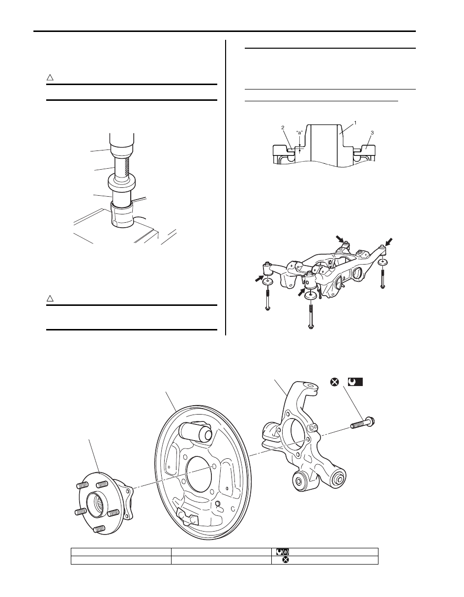
1) Press-fit rear suspension frame bushing (2) by using 

press (1) and special tool.

CAUTION

!


Be sure to use new bushing.


Special tool
(A):  09913–75510

2) Install rear suspension frame stopper (3) to rear 

suspension frame bushing (1) and press-fit upper 
mount stopper washer (2) by using press with 
bearing installer.

CAUTION

!


Be sure to use new upper mount stopper 
washer and rear suspension frame stopper.


NOTE
Use bearing installer in dimensions of outer 
diameter 43.0 to 49.0 mm (1.69 to 1.92 in.), 
inner diameter 41.0 mm (1.61 in.) or more and 
length 21.0 mm (0.82 in.) or more.


Clearance “a” between washer and bushing
“a”: 1.5 mm (0.059 in.)

Rear Suspension Frame, Bushing and Pad 
Check

S6JB0A2306023

Inspect for cracks, deformation or damage. If any faulty 
condition is found, replace.

Rear Wheel Hub Assembly and Rear Suspension Knuckle Components

S6JB0A2306024

1

(A)

2

I5JB0A230085-01

I5JB0A230080-01

I5JB0A230056-02

1

2

3

4

(a)

I6JB0A230007-01

1. Rear wheel hub assemble

3. Rear suspension knuckle

: 50 N

⋅m (5.0 kgf-m, 36.5 lb-ft)

2. Back plate

4. Rear wheel hub housing bolt

: Do not reuse.

Rear Suspension:  2C-24

Rear Wheel Hub Assembly Removal and 
Installation

S6JB0A2306025

Removal

1) Hoist vehicle and remove rear wheels.
2) Uncaulk rear axle nut (1).
3) Pull up parking brake lever fully and remove rear 

axle nut (1).

4) Remove rear break shoe referring to “Rear Brake 

Shoe Removal and Installation in Section 4C”.

5) Disconnect brake pipe (1) from wheel cylinder (2) 

and put wheel cylinder bleeder plug cap (3) onto 
pipe to prevent fluid from spilling.

6) Loosen parking cable cap nut (1).

7) Removal rear wheel hub housing bolts (1) and then 

remove rear wheel hub assembly and back plate.

8) Refer to Step 8) of “Removal” in “Front Wheel Hub 

Assembly Removal and Installation in Section 2B” to 
remove hub bolts since the rear wheel hub assembly 
is the same as the front wheel hub assembly.

Installation

1) Refer to Step 1) of “Installation” in “Front Wheel Hub 

Assembly Removal and Installation in Section 2B” to 
install hub bolts since the rear wheel hub assembly 
is the same as the front wheel hub assembly.

2) Apply grease to end face of inner ring (2) before rear 

wheel hub (1) installation.

CAUTION

!


Do not apply the grease to the encoder 
section to avoid the encoder malfunction.


“A”:  Grease 99000–25010 (SUZUKI Super 
Grease A)

I5JB0A230058-01

1

2

3

I5JB0A230059-01

1

I5JB0A230060-01

1

1

I5JB0A230061-01

1

2, "A"

I5JB0A220018-01

2C-25 Rear Suspension: 

3) Install rear wheel assembly and back plate to rear 

suspension knuckle and tighten rear wheel hub 
housing new bolts (1) to specified torque.

Tightening torque
Rear wheel hub housing bolt (a):  50 N·m (5.0 
kgf-m, 36.5 lb-ft)

4) Tighten parking cable cap nut (1) to specified torque.

Tightening torque
Parking cable cap nut  (a):  11 N·m (1.1 kgf-m, 8.0 
lb-ft)

5) Connect brake pipe (1) to wheel cylinder (2) and 

tighten brake pipe flare nut (1) to specified torque 
and install bleeder plug cap (3) taken off pipe back to 
bleeder plug.

Tightening torque
Brake pipe flare nut (a):  16 N·m (1.6 kgf-m, 11.5 
lb-ft)

6) Install rear break shoe referring to “Rear Brake Shoe 

Removal and Installation in Section 4C”.

7) Pull up parking brake lever fully and tighten new rear 

axle nut (1) to specified torque.

Tightening torque
Rear axle nut (a):  220 N·m (22.0 kgf-m, 159.5 lb-
ft)

8) Caulk rear axle nut (1).

CAUTION

!


Be careful while calking nut so that no crack 
will occur in calked part of nut. Cracked nut 
must be replaced with new one.


9) Fill reservoir with brake fluid and bleed brake 

system. Refer to “Air Bleeding of Brake System in 
Section 4A”
.

10) Upon completion of all jobs, depress brake pedal 

with about 30 kg (66 lbs) load a few times so as to 
obtain proper drum-to-shoe clearance. Adjust 
parking brake cable. Refer to “Parking Brake Check 
and Adjustment in Section 4D”.

11) Install rear wheels.

12) Check to ensure that brake drum is free from 

dragging and proper braking is obtained.

13) Lower hoist and tighten rear wheel bolts to specified 

torque.

Tightening torque
Wheel nut:  100 N·m (10.0 kgf-m, 72.5 lb-ft)

14) Perform brake test (foot brake and parking brake).
15) Check each installed part for fluid leakage.

1,(a)

1,(a)

I5JB0A230062-01

1,(a)

I5JB0A230063-01

1,(a)

2

3

I5JB0A230064-01

I5JB0A230065-01

Rear Suspension:  2C-26

Rear Wheel Hub Assembly, Wheel Bearing and 
Wheel Stud Inspection

S6JB0A2306026

• Wheel bearing and wheel hub form a solid unit.
• When wheel bearing is found defective and its 

replacement is necessary, replace hub assembly.

Rear Wheel Disc, Nut and Bearing Check

S6JB0A2306027

• Inspect each wheel disc for dents, distortion and 

cracks.
A disc in badly damaged condition must be replaced.

• Check wheel nuts for tightness and, as necessary, 

retighten to specification.

Tightening torque
Wheel nut (a):  100 N·m (10.0 kgf-m, 72.5 lb-ft)

• Check wheel bearings for wear. When measuring 

thrust play, apply a dial gauge to spindle cap center. If 
thrust play exceeds limit, replace bearing.

Rear wheel bearing thrust play “a”
Limit: 0.1 mm (0.004 in.)

• By rotating wheel actually, check wheel bearing for 

noise and smooth rotation. If it is defective, replace 
bearing.

Rear Suspension Knuckle Removal and 
Installation 

S6JB0A2306028

Removal

1) Hoist vehicle and remove rear wheels.
2) Remove rear wheel hub assembly referring to “Rear 

Wheel Hub Assembly Removal and Installation”.

3) Remove wheel speed sensor (1).

4) Loosen rear brake hose bracket bolt (1).

I5JB0A230066-01

(a)

I5JB0A220029-01

I2RH01230011-01

I2RH01230012-01

1

I5JB0A230067-01

1

I5JB0A230068-01


Content   ..  223  224  225  226   ..