Suzuki Grand Vitara JB416 / JB420 / JB419. Manual - part 211
 

  Index      Suzuki     Suzuki Grand Vitara JB416 / JB420 / JB419 - service repair manual 2007 year


Search            


Content   ..  209  210  211  212   ..


Suzuki Grand Vitara JB416 / JB420 / JB419. Manual - part 211


1K-4 Exhaust System: For Petrol Engine Model

Exhaust Manifold Removal and Installation (For 
M16 Engine Model)

S6JB0A1B16002

Removal

WARNING

!


To avoid danger of being burned, do not 
service exhaust system while it is still hot. 
Service should be performed after system 
cools down.


1) Disconnect negative cable at battery.
2) Remove exhaust pipe No.1 bracket.
3) Remove exhaust manifold (1) and its gasket from 

cylinder head.

Installation

1) Install new gasket to cylinder head and exhaust pipe 

No.1. Then install exhaust manifold.
Tighten manifold bolts (1) and nuts (2) to specified 
torque.

Tightening torque
Exhaust manifold bolt and nut (a):  50 N·m (5.0 
kgf-m, 36.5 lb-ft)

NOTE
Be sure to install exhaust manifold bolts and 
nuts to proper location referring to “Exhaust 
System Components: For Petrol Engine 
Model”.


2) Install exhaust pipe No.1 bracket (1).

Tightening torque
Exhaust pipe No.1 bracket bolt and nut (a):  50 
N·m (5.0 kgf-m, 36.5 lb-ft)

3) Connect negative cable at battery.
4) Check exhaust system for exhaust gas leakage.

Exhaust Manifold Removal and Installation (For 
J20 Engine Model)

S6JB0A1B16003

Removal

WARNING

!


To avoid danger of being burned, do not 
service exhaust system while it is still hot. 
Service should be performed after system 
cools down.


1) Relieve fuel pressure in fuel feed line according to 

“Fuel Pressure Relief Procedure: For Petrol Engine 
Model in Section 1G”.

2) Disconnect negative cable at battery.
3) Drain coolant referring to “Cooling System Draining: 

For Petrol Engine Model in Section 1F”.

4) Disconnect fuel hoses (2) from fuel pipes (1).
5) Disconnect water outlet pipe (3) from radiator inlet 

hose.

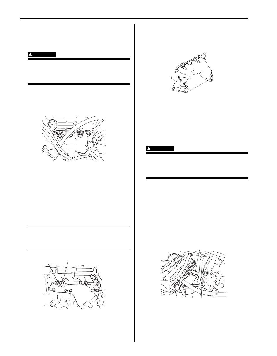
6) Remove exhaust manifold cover (4).

1

I5JB0A1B1004-01

2, (a)

1, (a)

I5JB0A1B1001-01

I5JB0A1B1009-01

3

2

1

4

2

I5JB0A1B1005-01

Exhaust System: For Petrol Engine Model 1K-5

7) Remove exhaust pipe No.1 bracket (1).
8) Remove exhaust manifold (2) and its gasket (3) from 

cylinder head.

Installation

1) Install new gasket (1) to cylinder head and exhaust 

pipe No.1. Then install exhaust manifold (2).
Tighten manifold bolts (4) and nuts (5) to specified 
torque.

Tightening torque
Exhaust manifold bolt and nut (b):  50 N·m (5.0 
kgf-m, 36.5 lb-ft)

NOTE
Be sure to install exhaust manifold bolts and 
nuts to proper location referring to “Exhaust 
System Components: For Petrol Engine 
Model”.


2) Install exhaust pipe No.1 bracket (3) to exhaust 

manifold.
Tighten nuts to specified torque.

Tightening torque
Exhaust No.1 pipe nut (a):  50 N·m (5.0 kgf-m, 
36.5 lb-ft)

3) Install exhaust manifold cover (1).
4) Connect water outlet pipe (2) from radiator inlet 

hose.

5) Connect fuel pipe (3) from fuel hoses.

6) Refill cooling system referring to “Cooling System 

Flush and Refill: For Petrol Engine Model in Section 
1F”.

7) Connect negative cable at battery.
8) Verify that there is no fuel leakage, coolant leakage 

and exhaust gas leakage at each connection.

Exhaust Pipe and Muffler Removal and 
Installation

S6JB0A1B16004

For replacement of exhaust pipe, be sure to hoist vehicle 
and observe WARNING under “Exhaust System 
Components: For Petrol Engine Model” 
and the 
following.

WARNING

!


To avoid danger of being burned, do not 
service exhaust system while it is still hot. 
Service should be performed after system 
cools down.


CAUTION

!


Exhaust manifold have three way catalytic 
converter in it, it should not be exposed to 
any impulse.
Be careful not to drop it or hit it against 
something.


• Tighten bolts and nuts to specified torque when 

reassembling. Refer to “Exhaust System 
Components: For Petrol Engine Model”.

• After installation, start engine and check each joint of 

exhaust system for leakage.

I5JB0A1B1006-01

I5JB0A1B1007-04

3

2

1

I5JB0A1B1008-01

1K-6 Exhaust System: For Petrol Engine Model

Specifications

Tightening Torque Specifications

S6JB0A1B17001

NOTE
The specified tightening torque is also described in the following.
“Exhaust System Components: For Petrol Engine Model”


Reference:
For the tightening torque of fastener not specified in this section, refer to “Fastener Information in Section 0A”.

Fastening part

Tightening torque

Note

N

m

kgf-m

lb-ft

Exhaust manifold bolt and nut

50

5.0 

36.5

)

 / )

Exhaust pipe No.1 bracket bolt and nut

50

5.0 

36.5

)

Exhaust No.1 pipe nut

50

5.0 

36.5

)

Exhaust System: For Diesel Engine Model 1K-7

For Diesel Engine Model

General Description

Exhaust System Description

S6JB0A1B21001

The exhaust system consists of an exhaust manifold, a 
turbo charger, a catalytic converter in a catalyst case, a 
diesel particurate filter (if equipped), an exhaust pipes, a 
muffler and seals, gasket and etc.
The catalytic converter is an emission control device 
added to the exhaust system to reduce the levels of 
Hydrocarbon (HC) and Carbon Monoxide (CO) in the 
exhaust gas.

Diesel Particurate Filter Description

S6JB0A1B21002

The diesel particurate filter is emission control device 
added to the exhaust system after catalytic converter, 
and it accumulates the diesel particular in the exhaust 
gas.
The diesel particurate filter is made up of a special 
ceramic monolith filled with a precious metal.

Diagnostic Information and Procedures

Exhaust System Check

S6JB0A1B24001

WARNING

!


To avoid the danger of being burned, do not 
touch the exhaust system when the system is 
hot. Any service on the exhaust system 
should be performed when the system is 
cool.


At every interval of periodic maintenance service, and 
when vehicle is raised for other service, check exhaust 
system as follows:
• Check rubber mountings for damage, deterioration, 

and out of position.

• Check exhaust system for leakage, loose connection, 

dent and damage.

• If bolts or nuts are loosened, tighten them to specified 

torque referring to “Exhaust System Components: For 
Diesel Engine Model”.

• Check nearby body areas damaged, missing, or 

mispositioned part, open seam, hole connection or 
any other defect which could permit exhaust fumes to 
seep into vehicle.

• Make sure that exhaust system components have 

enough clearance from underbody to avoid 
overheating and possible damage to passenger 
compartment carpet.

• Any defect should be fixed at once.

IYSY011B0003-01


Content   ..  209  210  211  212   ..