Suzuki Grand Vitara JB416 / JB420 / JB419. Manual - part 201
 

  Index      Suzuki     Suzuki Grand Vitara JB416 / JB420 / JB419 - service repair manual 2007 year


Search            


Content   ..  199  200  201  202   ..


Suzuki Grand Vitara JB416 / JB420 / JB419. Manual - part 201


1I-12 Starting System: For Diesel Engine Model

Diagnostic Information and Procedures

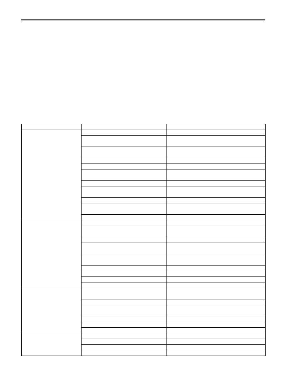
Cranking System Symptom Diagnosis

S6JB0A1924001

Possible symptoms due to starting system trouble would be as follows:
• Starting motor does not run (or runs slowly)
• Starting motor runs but fails to crank engine
• Abnormal noise is heard
Proper diagnosis must be made to determine exactly where the cause of each trouble lies.....in battery, wiring harness, 
(including starting motor switch), starting motor or engine.
Do not remove motor just because starting motor does not run. Check the following items and narrow down scope of 
possible causes.

1) Condition of trouble
2) Tightness of battery terminals (including ground cable connection on engine side) and starting motor terminals
3) Discharge of battery
4) Mounting of starting motor

Condition

Possible cause

Correction / Reference Item

Motor not running – No 
operating sound of 
magnetic switch

Battery run down

Recharge battery.

Battery voltage too low due to battery 
deterioration

Replace battery.

Poor contact in battery terminal 
connection

Retighten or replace.

Loose grounding cable connection

Retighten.

Fuse set loose or blown off

Tighten or replace.

Poor contacting action of ignition switch 
and magnetic switch

Replace.

Lead wire coupler loose in place

Retighten.

Open-circuit between ignition switch and 
magnetic switch

Repair.

Open-circuit in pull-in coil

Replace magnetic switch.

Brushes are seating poorly or worn 
down

Repair or replace.

Poor sliding or plunger and/or pinion

Repair.

Motor not running – 
Operating sound of 
magnetic switch heard

Battery run down

Recharge battery.

Battery voltage too low due to battery 
deterioration

Replace battery.

Loose battery cable connections

Retighten.

Burnt main contact point, or poor 
contacting action of magnetic switch

Replace magnetic switch.

Brushes are seating poorly or worn 
down

Repair or replace.

Weakened brush spring

Replace starting motor.

Burnt commutator

Replace starting motor.

Layer short-circuit of armature

Replace starting motor.

Crankshaft rotation obstructed

Repair.

Starting motor running, 
but too slow (small 
torque) – Battery and 
wiring are satisfactory

Insufficient contact of magnetic switch 
main contacts

Replace magnetic switch.

Layer short-circuit of armature

Replace starting motor.

Disconnected, burnt or worn 
commutator

Replace starting motor.

Worn brushes

Replace starting motor.

Weakened brush springs

Replace starting motor.

Burnt or abnormally worn end bush

Replace starting motor.

Starting motor running, 
but not cranking engine

Worn pinion tip

Replace over-running clutch.

Poor sliding of over-running clutch

Repair.

Over-running clutch slipping

Replace over-running clutch.

Worn teeth of ring gear

Replace flywheel (M/T).

Starting System: For Diesel Engine Model 1I-13

Starting Motor Performance Test

S6JB0A1924002

CAUTION

!


Each test must be performed within 3 – 5 
seconds to avoid coil from burning.


Pull-In Test

1) Connect battery to magnetic switch as shown.
2) Check that plunger and pinion move outward. If 

plunger and pinion don’t move, replace magnetic 
switch.

NOTE
Before testing, disconnect lead wire from 
terminal “M”.


Hold-In Test

1) While connected as above with plunger out, 

disconnect negative lead (2) from terminal “M” (1).

2) Check that plunger and pinion remain out. If plunger 

and pinion return inward, replace magnetic switch.

Plunger and Pinion Return Test

1) Disconnect negative lead (1) from switch body (2).
2) Check that plunger and pinion return inward. If 

plunger and pinion don’t return, disassemble and 
inspect starting motor.

Noise

Abnormally worn bearing

Replace front housing.

Worn pinion or worn teeth of ring gear

Replace over-running clutch or flywheel (M/T).

Poor sliding of pinion (failure in return 
movement)

Repair or replace.

Worn internal or planetary gear teeth

Replace.

Lack of oil in each part

Lubricate.

Starting motor does not 
stop running

Fused contact points of magnetic switch Replace magnetic switch.
Short-circuit between turns of magnetic 
switch coil (layer short-circuit)

Replace magnetic switch.

Failure of returning action in ignition 
switch

Replace.

Condition

Possible cause

Correction / Reference Item

1. Terminal “S”
2. Terminal “M”
3. Lead wire (switch to motor)

1

2

3

I5JB0B190002-01

1

2

I5JB0B190003-01

2

1

I5JB0B190004-01

1I-14 Starting System: For Diesel Engine Model

No-Load Performance Test

1) Connect battery and ammeter to starter as shown.
2) Check that starter rotates smoothly and steadily with 

pinion moving out. Check that ammeter indicates 
specified current.

Specified current (no-load performance test)
90A MAX. at 11V

NOTE
Use wires as thick as possible and tighten 
each terminal fully.


Repair Instructions

Starting Motor Components

S6JB0A1926005

A

I5JB0B190005-01

(a)

2

6

5

7

8

9

12

11

13

14

1

15

I5JB0B190006-02

1. Front housing

5. Planetary carrier shaft assembly

9. Pin

13. Over-running clutch

2. Yoke

6. Plunger / lever assembly

10. Magnetic switch inner bolt

14. Pinion stop ring 

Starting System: For Diesel Engine Model 1I-15

Starting Motor Dismounting and Remounting

S6JB0A1926001

WARNING

!


To avoid danger of being burned, do not 
service exhaust system while it is still hot. 
Service should be performed after system 
cools down.


1) Disconnect negative (–) cable at battery.
2) Remove air cleaner outlet hose.
3) Remove catalytic converter referring to “Exhaust 

System Components: For Diesel Engine Model in 
Section 1K”
.

4) Disconnect magnetic switch lead wire (3) and battery 

cable (4) from starting motor terminals.

5) Remove 3 starting motor mount bolts (2).
6) Remove starting motor (1).
7) To install, reverse the above procedure.

Starting Motor Disassembly and Assembly

S6JB0A1926002

Disassembly

NOTE
Do not clamp yoke in a vise or strike it with a 
hammer during repair operations.


1) Disconnect lead wire from terminal “M” (1).
2) Loosen through bolts (2).

3) Loosen magnetic switch screw (1) and then remove 

front housing (2).

4) Put match marks (1) on magnetic switch (2) and 

planetary carrier shaft assembly (3) to install the 
magnetic switch correctly in position.

5) Loosen magnetic switch inner screw (4) and then 

remove magnetic switch (2) and spring (5).

CAUTION

!


Don’t disassemble this switch. If defective, 
replace as a complete assembly.


6) Remove pin (1) and then remove from lever (2) and 

then plunger / lever assembly.

3. Magnetic switch bolt

7. Spring

11. Nut

15. Snap ring

4. Through bolt

8. Magnetic switch

12. Washer

: Do not reuse.

: 55 N

⋅m (5.5 kg-m, 40.0 lb-ft)

: 8  N

⋅m (8.0 kg-m, 6.0lb-ft)

(a)

(a)

2,

2,

1

(b)

3

4

I5JB0B190007-01

1

2

I5JB0B190008-01

1

2

I5JB0B190009-01

1

2

3

4

4

5

I5JB0B190010-01

1

2

I5JB0B190011-01


Content   ..  199  200  201  202   ..