Suzuki Grand Vitara JB416 / JB420 / JB419. Manual - part 194
 

  Index      Suzuki     Suzuki Grand Vitara JB416 / JB420 / JB419 - service repair manual 2007 year


Search            


Content   ..  192  193  194  195   ..


Suzuki Grand Vitara JB416 / JB420 / JB419. Manual - part 194


1G-49 Fuel System: For Diesel Engine Model

3) Hoist vehicle, and remove clamp (2) and fuel filler 

hose (1) from fuel filler neck.

4) Remove fuel tank inlet valve (1) using flat head rod 

(2) or the like.

CAUTION

!


Be careful not to damage fuel tank inlet valve 
(1) with flat head rod (2) or the like.


Installation

1) Install fuel tank inlet valve (1) to fuel tank.

2) Install fuel filler hose (1) to fuel tank and secure it 

with clamp (2).
For proper installation, refer to “Fuel Hose 
Disconnecting and Reconnecting: For Diesel Engine 
Model”.

3) Lower vehicle and install fuel filler cap.

Fuel Tank Inlet Valve Inspection

S6JB0A1726016

Check fuel tank inlet valve for the following.
If any damage or malfunction is found, replace.
• Damage
• Smooth opening and closing

Fuel Pump Assembly Removal and Installation

S6JB0A1726019

WARNING

!


Before servicing fuel system, be sure to 
observe “Precautions on Fuel System 
Service: For Diesel Engine Model”.


Removal

1) Remove fuel tank from vehicle. Refer to “Fuel Tank 

Removal and Installation: For Diesel Engine Model”.

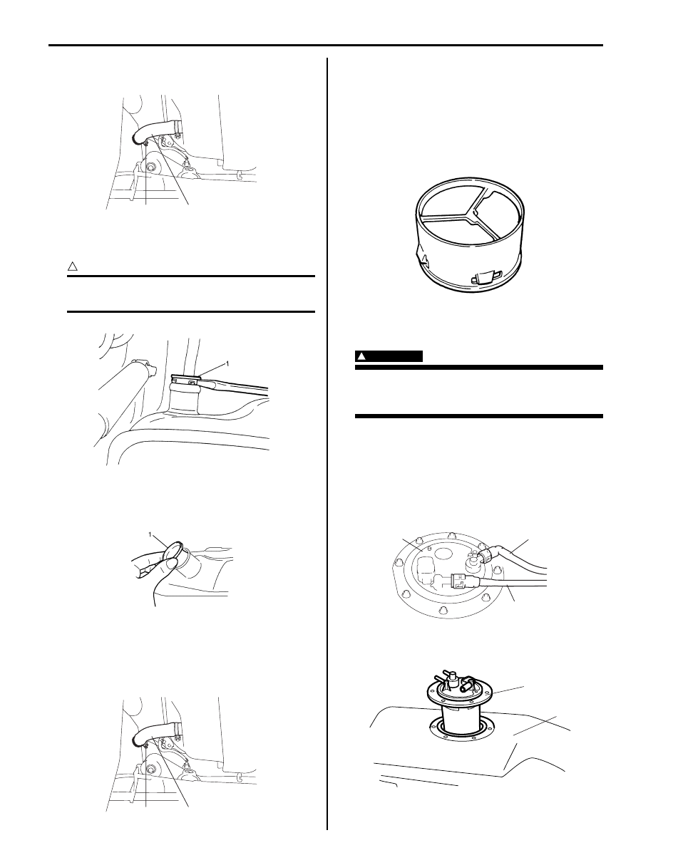
2) Disconnect fuel feed pipe (1) and fuel return pipe (3) 

from fuel pump assembly (2) referring to “Fuel Hose 
Disconnecting and Reconnecting: For Diesel Engine 
Model”
.

3) Remove fuel pump assembly (1) from fuel tank (2) 

and disconnect suction hose.

1

2

I5JB0A171014-01

I2RH0B170017-01

I2RH0B170018-01

1

2

I5JB0A171014-01

I2RH0B170019-01

3

1

2

I5JB0A171024-01

1

2

I3RM0A170021-01

Fuel System: For Diesel Engine Model 1G-50

Installation

CAUTION

!


When connecting joint, clean outside surface 
of pipe where joint is to be inserted, push 
joint into pipe till joint lock clicks and check 
to ensure that pipes are connected securely, 
or fuel leak may occur.


1) Clean mating surfaces of fuel pump assembly (1) 

and fuel tank.

2) Put plate (2) on fuel pump assembly (1) by matching 

the protrusion of fuel pump assembly (3) to plate 
hole (4) as shown.

3) Connect suction hose to fuel pump assembly (1), 

and install new gasket (2) and fuel pump assembly 
with plate (3) to fuel tank (4).

Tightening torque
Fuel pump assembly bolt (a):  11 N·m (1.1 kgf-m, 
8.0 lb-ft)

4) Connect fuel feed pipe (1) (pipe joint) and fuel return 

pipe (3) (pipe joint) to fuel pump assembly (2).

5) Install fuel tank to vehicle. Refer to “Fuel Tank 

Removal and Installation: For Diesel Engine Model”.

Fuel Pump Inspection

S6JB0A1726043

• Check fuel pump assembly for damage.
• Check fuel suction filter for evidence of dirt and 

contamination.
If present, replace or clean and check for presence of 
dirt in fuel tank.

• For electrical circuit.

Main Fuel Level Gauge Removal and Installation

S6JB0A1726039

CAUTION

!


• Do not touch resister plate (1) and deform 

arm (2). It may cause main fuel level gauge 
to fail.

• Be very careful not to cause damage to 

fuel tube installed section (sealed section 
in bore). If it be damaged, replace it with 
new one, or fuel will leak from the part.


Removal

1) Remove fuel pump assembly from fuel tank referring 

to “Fuel Pump Assembly Removal and Installation: 
For Diesel Engine Model”.

2) Disconnect main fuel level gauge connector (3).
3) With pressing snap-fit part (2), remove main fuel 

level gauge (1) by sliding it in the arrow direction as 
shown in figure.

Installation
Reverse removal procedure for installation.

3

1

2

4

I5JB0A171025-01

3

1

2

(a)

4

I3RM0A170023-01

3

1

2

I5JB0A171024-01

1

2

I5JB0B170036-01

1

3

1

2

I5JB0B170037-01

1G-51 Fuel System: For Diesel Engine Model

Main Fuel Level Gauge Inspection

S6JB0A1726041

• Check main fuel level gauge for damage.
• For inspection of main fuel level gauge (1), refer to 

“Fuel Level Sensor Inspection in Section 9C”.

Sub Fuel Level Gauge Removal and Installation

S6JB0A1726040

CAUTION

!


Do not touch resister plate (1) and deform 
arm (2). It may cause sub fuel level gauge to 
fail.


Removal

1) Remove fuel tank from vehicle Referring to “Fuel 

Tank Removal and Installation: For Diesel Engine 
Model”

2) Disconnect sub fuel level gauge connector (1) 

referring to “Fuel Hose Disconnecting and 
Reconnecting: For Diesel Engine Model”.

3) Remove sub fuel level gauge (2).

Installation
Reverse removal procedure for installation noting the 
following.
• Replace O-ring with new one using care not to 

damage it.

• Apply thin coat of fuel to O-ring, and then install sub 

fuel level sensor.

Sub Fuel Level Gauge Inspection

S6JB0A1726042

• Check sub fuel level gauge for damage.
• For inspection of sub fuel level gauge (1), refer to 

“Fuel Level Sensor Inspection in Section 9C”.

1

I5JB0A171027-01

2

1

I5JB0A171028-01

2

2

1

I5JB0A171029-01

1

I5JB0A171030-01

Fuel System: For Diesel Engine Model 1G-52

Specifications

Tightening Torque Specifications

S6JB0A1727001

NOTE
The specified tightening torque is also described in the following.
“Fuel System Components: For Diesel Engine Model”
“Fuel Hose Disconnecting and Reconnecting: For Diesel Engine Model”
“Injection Pump Components: For Diesel Engine Model”


Reference:
For the tightening torque of fastener not specified in this section, refer to “Fastener Information in Section 0A”.

Fastening part

Tightening torque

Note

N

m

kgf-m

lb-ft

Fuel filter case bolt

5

0.5 

4.0

)

Common rail bolt

22

2.2 

16.0

)

High pressure pipe union nut (Type 2)

25

2.5 

18.0

)

 / )

High pressure pipe union nut (Common rail to 
fuel injector) (Type 3)

27

2.7 19.5

)

Common rail mounting bolt

22

2.2 

16.0

)

High pressure pipe union nut (Injection pump 
side) (Type 3)

27

2.7 19.5

)

High pressure pipe union nut (Common rail 
side) (Type 3)

37

3.7 27.0

)

Common rail bolt

25

2.5 

18.0

)

Throttle body to EGR valve pipe bolt and nut

21

2.1 

15.5

)

Injector cover bolt

8

0.8 

6.0

)

Fuel injector bracket bolt

25

2.5 

18.0

)

Injection pump bolt

30

3.0 

22.0

)

Injection pump pulley nut

70

7.0 

51.0

)

Injection pump front bracket bolt

Tighten 20 N

⋅m (0.2 kgf-m, 14.5 lb-ft) and 

80

° by the specified procedure.

)

Injection pump rear bracket to cylinder block 
bolt

44

4.4 32.0

)

Injection pump rear bracket to injection pump 
bolt (Type 2)

44

4.4 32.0

)

Injection pump rear bracket to injection pump 
bolt M8 (Type 3)

30

3.0 22.0

)

Injection pump rear bracket to injection pump 
bolt M6 (Type 3)

10

1.0 7.5

)

Fuel flow actuator bolt

Tighten 3 N

⋅m (0.3 kgf-m, 2.5 lb-ft) and 6 

N

⋅m (0.6 kgf-m, 4.5 lb-ft) by the specified 

procedure.

)

Fuel tank bolt

50

5.0 

36.5

)

Fuel filler hose clamp

2

0.2 

1.5

)

Fuel pump assembly bolt

11

1.1 

8.0

)


Content   ..  192  193  194  195   ..