Suzuki Grand Vitara JB416 / JB420 / JB419. Manual - part 190
 

  Index      Suzuki     Suzuki Grand Vitara JB416 / JB420 / JB419 - service repair manual 2007 year


Search            


Content   ..  188  189  190  191   ..


Suzuki Grand Vitara JB416 / JB420 / JB419. Manual - part 190


1G-33 Fuel System: For Diesel Engine Model

• Other than clamp around fuel tank

For Quick Joint
Disconnecting

1) Remove mud, dust and/or foreign material between 

pipe (1) and quick joint (2) by blowing compressed 
air.

2) Unlock joint lock by inserting special tool between 

pipe and quick joint.

Special tool
(A):  09919–47020

3) Disconnect quick joint from pipe.

Reconnecting
Insert quick joint to fuel pipe until they lock securely (a 
click is heard), and confirm that quick joint is not 
disconnected by hand.

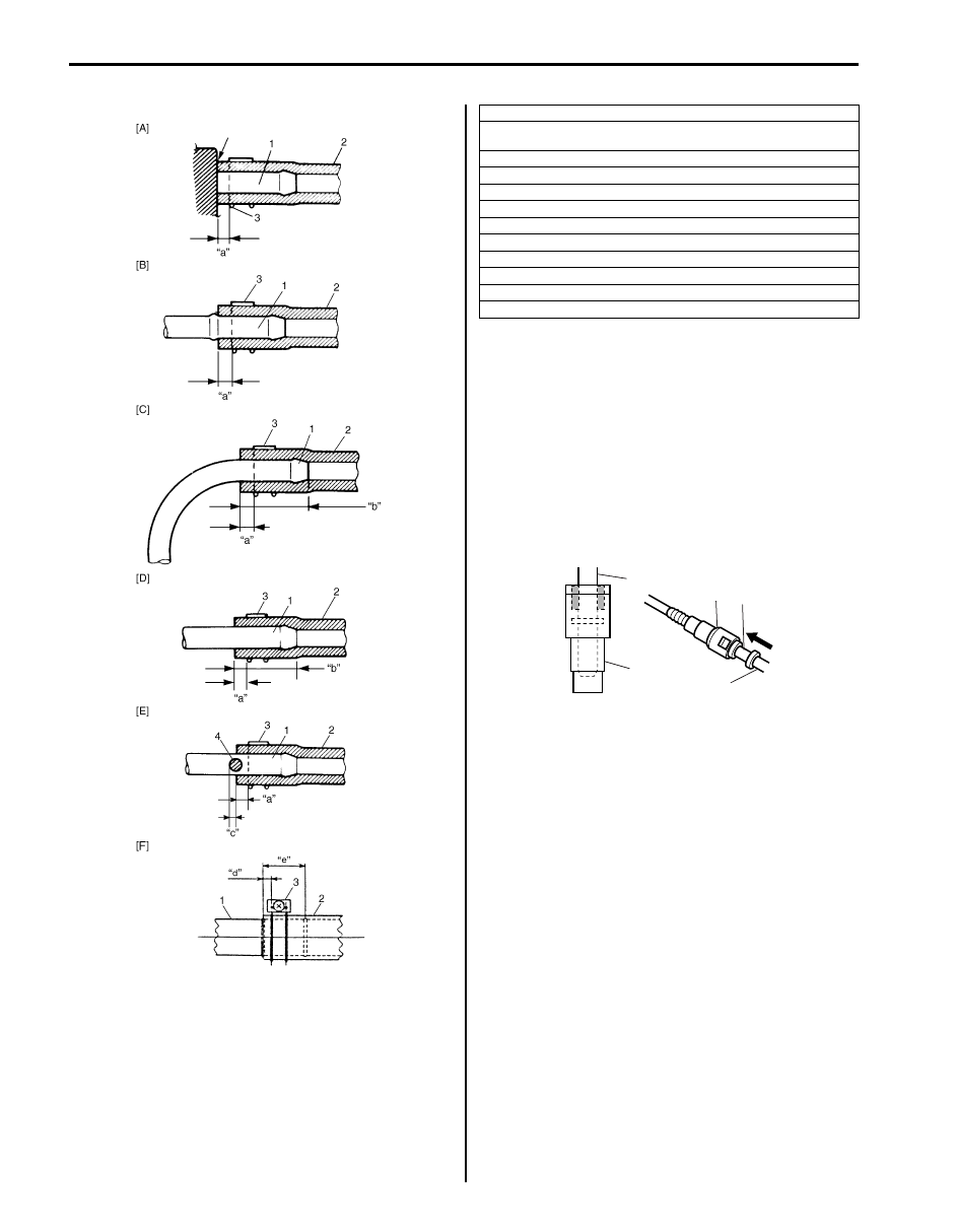
I3RM0A170001-01

[A]: With short pipe, fit hose as far as it reaches pipe joint as shown.
[B]: With the following type pipe, fit hose as far as its peripheral projection 

as shown.

[C]: With bent pipe, fit hose as its bent part as shown or till depth “b”.
[D]: With straight pipe, fit hose till depth “b”.

[E]: With red marked pipe, fit hose end reaches red mark on pipe.

[F]: For fuel tank filler hose, insert it to spool or welding-bead.

“a”: Clamp securely at a position 3 – 7 mm (0.12 – 0.27 in.) from hose end.
“b”: 20 – 30 mm (0.79 – 1.18 in.)

“c”: 0 – 5 mm (0 – 0.19 in.)

“d”: 5 – 12 mm (0.2 – 0.47 in.)
“e”: 40 mm (1.57 in.)

4. Red mark

1

2

1

2

(A)

I4RS0A170019-01

Fuel System: For Diesel Engine Model 1G-34

Fuel Lines Inspection

S6JB0A1726004

CAUTION

!


Due to the fact that fuel feed line is under 
high pressure, use special care when 
servicing it.


Visually inspect fuel lines for evidence of fuel leakage, 
hose crack and deterioration or damage.
Make sure all clamps are secure.
Replace parts as needed.

Fuel Pipe Removal and Installation

S6JB0A1726005

WARNING

!


Before servicing fuel system, be sure to 
observe “Precautions on Fuel System 
Service: For Diesel Engine Model”.


Removal

1) Disconnect negative (–) cable at battery.
2) Disconnect fuel pipe joint and fuel hose (1) from fuel 

pipe (2) at the front and rear of each fuel pipe 
referring to “Fuel Hose Disconnecting and 
Reconnecting: For Diesel Engine Model”.

3) Mark the location of clamps (3) and (4) on fuel pipes 

(2), so that the clamps can be reinstalled to where 
they were.

4) Remove pipes (2) with clamp (3) and (4) from 

vehicle.

5) Remove clamp (3) and (4) from pipes (2).

Installation

1) Install clamps to painted white location pipes. If 

clamp is deformed, its claw is bent or broken, 
replace it with new one.

2) Install pipes with pipe clamps to vehicle.
3) Connect fuel hoses and pipes to each pipe referring 

to “Fuel Hose Disconnecting and Reconnecting: For 
Diesel Engine Model”
.

4) Connect negative (–) cable at battery.
5) Check fuel leakage referring to “Fuel Leakage Check 

Procedure: For Diesel Engine Model”.

I4RH0A170005-01

[A]: 5 door model

[B]: 3 door model

A: Vehicle forward

I6JB0A172003-01

1G-35 Fuel System: For Diesel Engine Model

High Pressure Pipe Removal and Installation

S6JB0A1726027

WARNING

!


Before servicing fuel system, be sure to 
observe “Precautions on Fuel System 
Service: For Diesel Engine Model”.


Removal

CAUTION

!


A small amount of fuel may come out during 
removal of high pressure pipes, cover high 
pressure pipes with lint-free cloth.


1) Relief fuel pressure referring to “Fuel Pressure Relief 

Procedure: For Diesel Engine Model”.

2) Disconnect negative (–) cable at battery.
3) Remove engine cover.
4) Disconnect ventilation hose No.2 (1) from ventilation 

pipe No.2 (3). 

5) Disconnect ventilation hose No.4 (2) from oil vapor 

recirculation valve (4). 

6) Disconnect boost pressure sensor connector (5) and 

inlet throttle valve connector (6).

7) Remove vacuum pipe (7), throttle body (8) with 

throttle body to EGR valve pipe (9) and fuel injector 
cover (10).

8) Remove high pressure pipe as follows.

• For high pressure pipe between fuel injector and 

common rail
a. Loosen high pressure pipe union nut (1) using 

special tool and wrench.

CAUTION

!


When loosing union nut of injection side, 
hold union nut (2) with wrench (3) as shown 
in figure. Otherwise, pipe way bend or break.


Special tool
(A):  09911–75410

10

4

5

6

7

9

2

1

8

3

I5JB0B170041-01

[A]: Injector side

[B]: Common rail side

3

2

1

(A)

(A)

1

[B]

[A]

I5JB0B170011-01

Fuel System: For Diesel Engine Model 1G-36

• For high pressure pipe between injection pump and 

common rail
a. Loosen high pressure pipe union nut (1) using 

special tool and wrench.

CAUTION

!


When loosing union nut of injection pump 
side, hold union nut (2) with wrench (3) as 
shown in figure.


Special tool
(A):  09911–75410

9) Clean and vacuum any contamination, and plug all 

joint part of disconnected fuel injection circuit with 
plug cap referring to “Precautions on Fuel System 
Service: For Diesel Engine Model”
.

Installation

CAUTION

!


• Do not touch pipes with wrench when 

tightening union nut to avoid a damage of 
high pressure pipe.

• In case of extension special tool combined 

with torque wrench, reading value of 
torque wrench is smaller than specified 
tightening torque. When using extension 
special tool, reading value should be 
calculated according to formula below.


Tightening torque formula.
M = T x L / (L + “a”)
M: Reading value using extension special tool
T: Specified tightening torque
L: Length of torque wrench
“a”: Length of special tool

Special tool
(A):  09911–75410
(B):  09911–75420

1) Loosen common rail mounting bolts fully in order not 

to install high pressure pipe under stress.

2) Install new high pressure pipes as follows.

[A]: Injection pump side (Type 2)

[C]: Common rail side

[B]: Injection pump side (Type 3)

I6JB0A172006-01

“a”: 35 mm (1.38 in.)

“b”: 23 mm (0.97 in.)

L

L1

1

(B)

(A)

(B)

"a"

"b"

I4RH0A170002-01


Content   ..  188  189  190  191   ..