Suzuki Grand Vitara JB416 / JB420 / JB419. Manual - part 178
 

  Index      Suzuki     Suzuki Grand Vitara JB416 / JB420 / JB419 - service repair manual 2007 year


Search            


Content   ..  176  177  178  179   ..


Suzuki Grand Vitara JB416 / JB420 / JB419. Manual - part 178


1F-9 Engine Cooling System: For Petrol Engine Model

Thermostat Removal and Installation (For J20 
Engine Model)

S6JB0A1616008

Removal

1) Drain coolant referring to “Cooling System Draining: 

For Petrol Engine Model”.

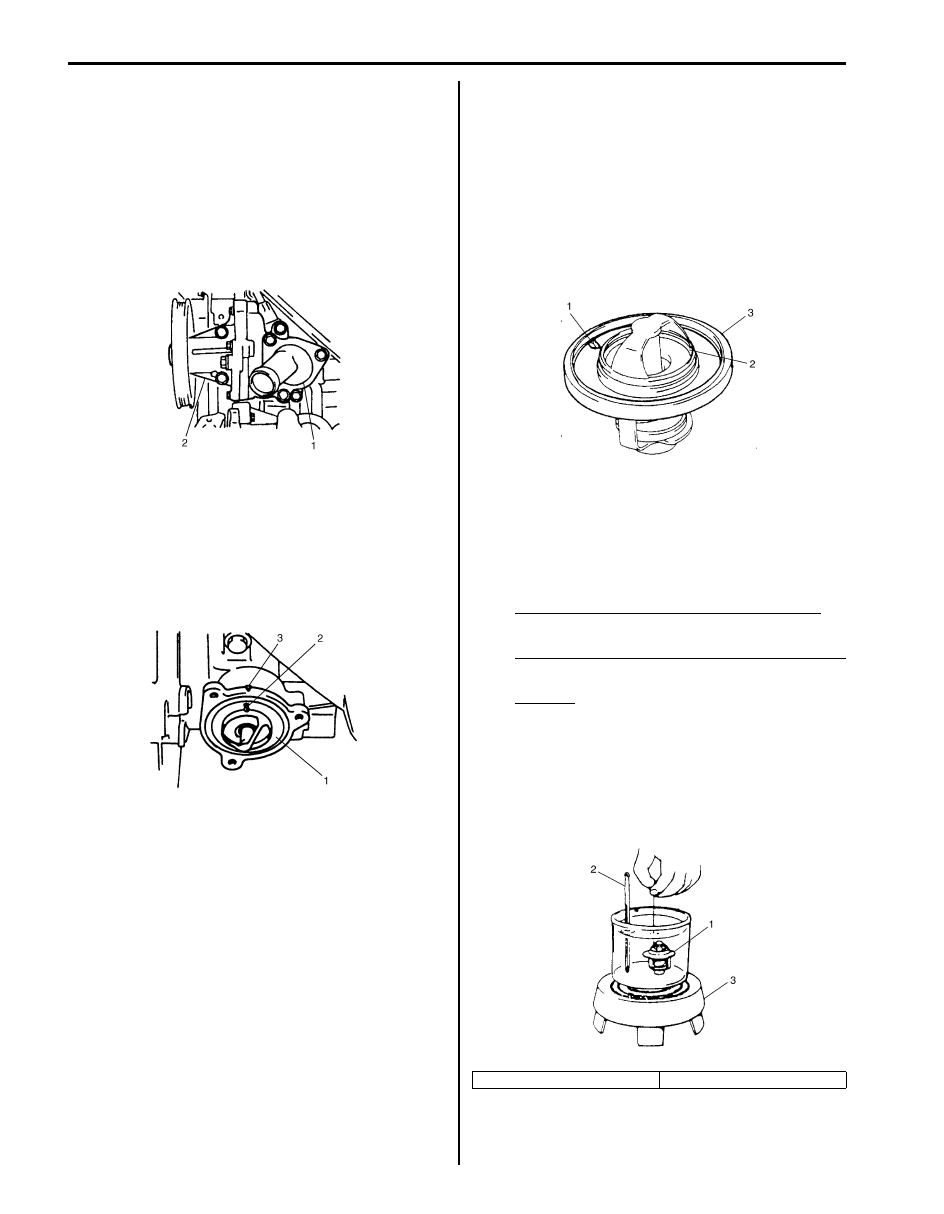
2) Disconnect radiator outlet hose from thermostat cap 

(1).

3) Remove thermostat cap (1) from water pump (2).
4) Remove thermostat from water pump (2).

Installation
Reverse removal procedure for installation noting the 
following points.
• When positioning thermostat (1) on water pump case, 

be sure to position it so that air bleed valve (2) comes 
at match mark (3) and into the recession of water 
pump case.

• Use new O-ring when installing.
• Refill cooling system referring to Step 7) to 17) of 

“Cooling System Flush and Refill: For Petrol Engine 
Model”.

• Verify that there is no coolant leakage at each 

connection.

Thermostat Inspection

S6JB0A1616009

• Make sure that air bleed valve (1) of thermostat is 

clean.
Should this valve be clogged, engine would tend to 
overheat.

• Check to make sure that valve seat (2) is free from 

foreign matters which would prevent valve from 
seating tight.

• Check thermostat seal (3) for breakage, deterioration 

or any other damage.

• Check thermostatic movement of wax pellet as 

follows:
a. Immerse thermostat (1) in water, and heat water 

gradually.

b. Check that valve starts to open at specific 

temperature.

Temperature at which valve begins to open
80 – 84 

°C (176 – 183 °F)

Temperature at which valve become fully open
95 – 97 

°C (203 °F)

Valve lift
More than 8 mm at 95 

°C (203 °F)

If valve starts to open at a temperature substantially 
below or above specific temperature, thermostat unit 
should be replaced with a new one. Such a unit, if 
reused, will bring about overcooling or overheating 
tendency.

I5JB0A161009-01

I2RH01160010-01

2. Thermometer

3. Heater

I3RM0A160008-01

I2RH01160012-01

Engine Cooling System: For Petrol Engine Model 1F-10

Radiator Cooling Fan Motor On-Vehicle 
Inspection

S6JB0A1616010

1) Check main and/or sub fan operation of radiator 

cooling fan as follows.
a) Connect battery to main fan motor coupler 

(coupler color: black) or sub fan motor coupler 
(coupler color: gray) as shown in figure.

b) Check that radiator cooling fan rotates smoothly.

If any abnormality is found, replace fan motor.

Reference: Fan motor specified current at 12 
V
Main fan operation: 7.4 – 10.9 A
Sub fan operation: 6.7 – 9.7 A

Radiator Cooling Fan Relay Inspection

S6JB0A1616011

1) Disconnect negative (–) cable at battery.
2) Remove radiator cooling fan relay No.1 (1), No.3 (2) 

and/or No.2 (3) from relay box.

3) Check radiator cooling fan relay No.1 (1) and No.3 

(2) as follows.
a) Check that there is no continuity between 

terminals “C” and “D”. If there is continuity, 
replace relay.

b) Connect battery positive (+) terminal to terminal 

“B” of relay.

c) Connect battery negative (–) terminal to terminal 

“A” of relay.

d) Check continuity between terminals “C” and “D”. 

If there is no continuity, replace relay.

4) Check radiator cooling fan relay No.2 (3) as follows.

a) Check that there is no continuity between 

terminals “G” or “H” and “F”. If there is continuity, 
replace relay.

b) Check continuity between terminals “I” and “H”. If 

there is no continuity, replace relay.

c) Connect battery positive (+) terminal to terminal 

“F” of relay.

d) Connect battery negative (–) terminal to terminal 

“E” of relay.

e) Check continuity between terminals “G” and “H”. 

If there is no continuity, replace relay.

1. Main fan motor
2. Sub fan motor

I5JB0A161012-02

I5JB0A161011-01

1

2

3

“D”

“B”

“A”

“C”

“A”

“B”

“D”

“C”

“H”

“F”

“E”

“G”

“I”

“F”

“E”

“H”

“I”

“G”

I5JB0A161017-01

1F-11 Engine Cooling System: For Petrol Engine Model

Radiator Cooling Fan Assembly Removal and 
Installation

S6JB0A1616012

Removal

1) Disconnect negative (–) cable at battery.
2) Disconnect connectors (1) of cooling fan motors.

3) With hose connected, detach P/S fluid reservoir with 

reservoir bracket.

4) Remove air cleaner case and air cleaner suction 

pipe (2).

5) Remove reservoir (1) from radiator.

6) Remove cooling fan assembly.

Installation
Reverse removal procedure for installation noting the 
following.
• Refill cooling system referring to Step 7) to 17) of 

“Cooling System Flush and Refill: For Petrol Engine 
Model”.

• After installation, verify there is no coolant leakage at 

each connection.

Radiator On-Vehicle Inspection and Cleaning

S6JB0A1616013

Inspection
Check radiator for leakage or damage. Straighten bent 
fins, if any.

Cleaning
Clean frontal area of radiator cores.

Radiator Removal and Installation

S6JB0A1616014

Removal

1) Disconnect negative cable at battery.
2) For A/T, drain A/T fluid referring to “A/T Fluid Change 

in Section 5A”.

3) Drain coolant.
4) Remove cooling fan assembly referring to “Radiator 

Cooling Fan Assembly Removal and Installation: For 
Petrol Engine Model”.

5) For A/T, remove A/T fluid cooler inlet and outlet 

hoses.

6) Remove radiator outlet hose from radiator.
7) Remove condenser bolts from condenser brackets.
8) Remove radiator from vehicle.

Installation
Reverse removal procedures, noting the following.
• Refill cooling system referring to Step 7) to 17) of 

“Cooling System Flush and Refill: For Petrol Engine 
Model”.

• After installation, verify there is no coolant leakage 

each connection.

• Refill A/T fluid referring to “A/T Fluid Change in 

Section 5A”.

1

I5JB0A161014-01

1

2

I5JB0A161015-01

I2RH01160014-01

Engine Cooling System: For Petrol Engine Model 1F-12

Water Pump Removal and Installation (For M16 
Engine Model)

S6JB0A1616015

Removal

1) Disconnect negative cable at battery.
2) Drain coolant.
3) Remove water pump and generator drive belt 

referring to “Water Pump and Generator Drive Belt 
Removal and Installation (For M16 Engine): For 
Petrol Engine Model in Section 1J”.

4) Remove water pump assembly (1).

Installation

1) Apply sealant to mating surface of water pump (1) as 

shown in the figure.

“A”:  Water tight sealant 99000–31250 (SUZUKI 
Bond No.1207F) 

Sealant quantity (to mating surface of water 
pump)
Width “a”: 3 mm (0.12 in.)
Height “b”: 2 mm (0.08 in.)

2) Install water pump assembly (1) to cylinder block 

and tighten bolts and nut to specified torque.

Tightening torque
Water pump bolt and nut (a):  25 N·m (2.5 kgf-m, 
18.0 lb-ft)

3) Install water pump pulley.
4) Install water pump and generator drive belt referring 

to “Water Pump and Generator Drive Belt Removal 
and Installation (For M16 Engine): For Petrol Engine 
Model in Section 1J”.

5) Install P/S pump and A/C compressor drive belt (if 

equipped) referring to “P/S Pump and A/C 
Compressor (If Equipped) Drive Belt Removal and 
Installation (M16A Engine Model) in Section 6C”.

6) Refill cooling system referring to Step 7) to 17) of 

“Cooling System Flush and Refill: For Petrol Engine 
Model”.

7) Connect negative cable at battery.
8) Check each part for leakage.

Water Pump Removal and Installation (For J20 
Engine Model)

S6JB0A1616016

Removal

1) Disconnect negative cable at battery.
2) Drain coolant referring to “Cooling System Draining: 

For Petrol Engine Model”.

3) Remove water pump and generator drive belt 

referring to “Water Pump and Generator Drive Belt 
Removal and Installation (For J20 Engine): For 
Petrol Engine Model in Section 1J”.

4) Remove thermostat referring to “Thermostat 

Removal and Installation (For J20 Engine Model): 
For Petrol Engine Model”.

I2RH0B160016-01

I3RM0A160016-01

I2RH0B160018-01


Content   ..  176  177  178  179   ..