Suzuki Grand Vitara JB416 / JB420 / JB419. Manual - part 174
 

  Index      Suzuki     Suzuki Grand Vitara JB416 / JB420 / JB419 - service repair manual 2007 year


Search            


Content   ..  172  173  174  175   ..


Suzuki Grand Vitara JB416 / JB420 / JB419. Manual - part 174


1E-25 Engine Lubrication System: For F9Q Engine

Installation

1) Remove oil, old sealant and dust from mating 

surface of upper oil pan, cylinder block and lower oil 
pan.

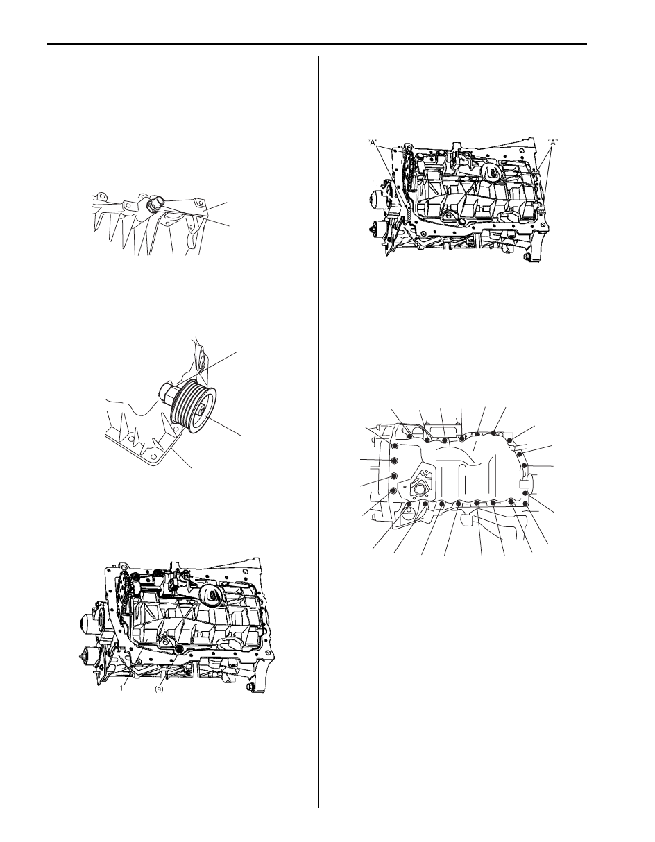
2) Install new ventilation hose No.3 union bolt (1) to 

upper oil pan (2), if necessary.

Tightening torque
Ventilation hose No.3 union bolt (a):  25 N·m (2.5 
kgf-m, 18.5 lb-ft)

3) Install accessory belt idler (1) with base (2) to upper 

oil pan (3), if removed.

Tightening torque
Idler base (a):  50 N·m (5.0 kgf-m, 36.5 lb-ft)

4) Install oil pan baffle plate (1), if removed.

Tightening torque
Oil pan baffle plate bolt (a):  24 N·m (2.4 kgf-m, 
17.5 lb-ft)

5) Apply sealant to hatched part of cylinder block, 

gasket holder plate and main bearing cap No.1 as 
shown in figure.

“A”:  Thread lock cement  (Loctite rhodorseal 
5661®)

6) Install upper oil pan (1) to cylinder block with new 

gasket, and tighten upper oil pan bolts evenly and 
gradually in numerical order (“1” through “22”) by 
repeating tightening sequence two or three times 
until specified torque is obtained.

Tightening torque
Upper oil pan bolt (a):  Tighten 15 N

m (1.5 kgf-m, 

11.0 lb-ft) by the specified procedure

1, “A”, (a)

2

I5JB0B150018-03

1

2

3

I5JB0B150019-01

I5JB0B150020-01

I5JB0B150022-01

“12”

“13”

“20”

“16”

“17”

“8”

“9”

“2”

“5”

“3”

“4”

(a), “1”

“10”

“11”

“18”

“19”

“14”

“15”

“6”

“7”

“22”

“21”

I5JB0B150023-01

Engine Lubrication System: For F9Q Engine 1E-26

7) Tighten transmission to engine bolts referring to 

“Manual Transmission Assembly Dismounting and 
Remounting: For Diesel Engine Model in Section 
5B”
.

8) Connect ventilation pipe No.1 (1) and ventilation 

hose No.3 (2) to upper oil pan with new O-ring.

Tightening torque
Ventilation pipe No.1 bolt (a):  10 N·m (1.0 kgf-m, 
7.5 lb-ft)

9) Install suspension frame referring to “Front 

Suspension Frame, Stabilizer Bar and/or Bushings 
Removal and Installation in Section 2B”.

10) Install fresh air vent union bolt (1) to lower oil pan 

with new gasket, if removed.

Tightening torque
Fresh air vent union bolt (a):  30 N·m (3.0 kgf-m, 
22.0 lb-ft)

11) Install lower oil pan (1) to upper oil pan with new 

gasket, and tighten lower oil pan bolts evenly and 
gradually in numerical order (“1” through “4”) by 
repeating tightening sequence two or three times 
until specified torque is obtained.

Tightening torque
Lower oil pan bolt (a):  Tighten 22 N

m (2.2 kgf-m, 

16.0 lb-ft) by the specified procedure

12) Install lower oil pan stiffener No.1 (1) and No.2 (2), 

and tighten lower oil pan stiffener No.1 and No.2 
bolts according to numerical order (“1” though “4”) as 
shown in figure.
Apply thread lock “A” to lower oil pan stiffener bolt 
marked “2”.

“A”:  Thread lock cement 99000–32030 (Thread 
Lock Cement Super 1303B)

Tightening torque
Lower oil pan stiffener bolt (a):  Tighten 32 N

(3.2 kgf-m, 23.5 lb-ft) by the specified procedure

1

2

(a)

I5JB0B150024-01

1, (a)

I5JB0B150025-01

1

(a), “2”

(a), “3”

(a), “4”

(a), “1”

I5JB0B150026-01

1

2


“A”, (a), “2”

(a), “3”

(a), “4”

(a), “1”

I5JB0B150027-01

1E-27 Engine Lubrication System: For F9Q Engine

13) Install oil pump strainer No.1 (1) and oil separator 

return pipe (2) with new O-rings.

Tightening torque
Oil pump strainer No.1 bolt (a):  10 N·m (1.0 kgf-
m, 7.5 lb-ft)
Oil separator oil return pipe (b):  12 N·m (1.2 kgf-
m, 9.0 lb-ft)

14) Install closure plate (1) with new gasket, and tighten 

closure plate bolts evenly and gradually in numerical 
order (“1” though “13”) by repeating tightening 
sequence two or three times until specified torque is 
obtained.

Tightening torque
Closure plate bolt (a):  Tighten 8 N

m (0.8 kgf-m, 

6.0 lb-ft) by the specified procedure

15) Connect lower oil pan hose (1) to oil separator return 

pipe.

16) Connect oil separator return hose (2) to oil separator 

return pipe.

17) Refill engine oil referring to “Engine Oil and Filter 

Change (Diesel Engine Model) in Section 0B”.

1

(b)

2

(a)

I5JB0B150028-01

1

“12”

“13”

“8”

“9”

“2”

“5”

“3”

“4”

(a), “1”

“10”

“11”

“6”

“7”

I5JB0B150029-01

1

2

I5JB0B150005-01

Engine Lubrication System: For F9Q Engine 1E-28

Oil Pump, Oil Pump Chain and Gasket Holder Plate Component

S6JB0A1536003

CAUTION

!


Never disassemble oil pump. Disassembly will spoil its original function. If faulty condition is found, 
replace it with new one.


Oil Pump, Oil Pump Chain and Gasket Holder 
Plate Removal and Installation

S6JB0A1536004

CAUTION

!


Never disassemble oil pump. Disassembly 
will spoil its original function. If faulty 
condition is found, replace it with new one.


Removal

1) Remove oil pan and oil pump strainer referring to “Oil 

Pan and Oil Pump Strainer Removal and Installation: 
For F9Q Engine”.

2) Remove oil pump (1) from cylinder block.

4

(a)

(b)

6

1

5

7

2

3

I5JB0B150043-01

1. Oil pump

: Do not disassemble.

4. Gasket holder plate

7. Oil pump chain tensioner

: Do not reuse.

2. Oil pump drive sprocket

5. Gasket holder plate gasket

: 24 N

⋅m (2.4 kgf-m, 17.5 lb-ft)

: Apply engine oil to sliding surface of 

each part.

3. Oil pump chain

6. Crankshaft oil seal

: 14 N

⋅m (1.4 kgf-m, 10.5 lb-ft)

1

I5JB0B150030-01


Content   ..  172  173  174  175   ..