Suzuki Grand Vitara JB416 / JB420 / JB419. Manual - part 158
 

  Index      Suzuki     Suzuki Grand Vitara JB416 / JB420 / JB419 - service repair manual 2007 year


Search            


Content   ..  156  157  158  159   ..


Suzuki Grand Vitara JB416 / JB420 / JB419. Manual - part 158


1D-158 Engine Mechanical: For F9Q Engine

EGR Pipe and EGR Cooler Removal and 
Installation

S6JB0A1436055

Removal

1) Remove engine assembly referring to “Engine 

Assembly Removal and Installation: For F9Q 
Engine”.

2) Remove catalytic converter referring to “Exhaust 

System Components: For Diesel Engine Model in 
Section 1K”
.

3) Remove thermostat assembly referring to 

“Thermostat Assembly Removal and Installation: For 
Diesel Engine Model in Section 1F”.

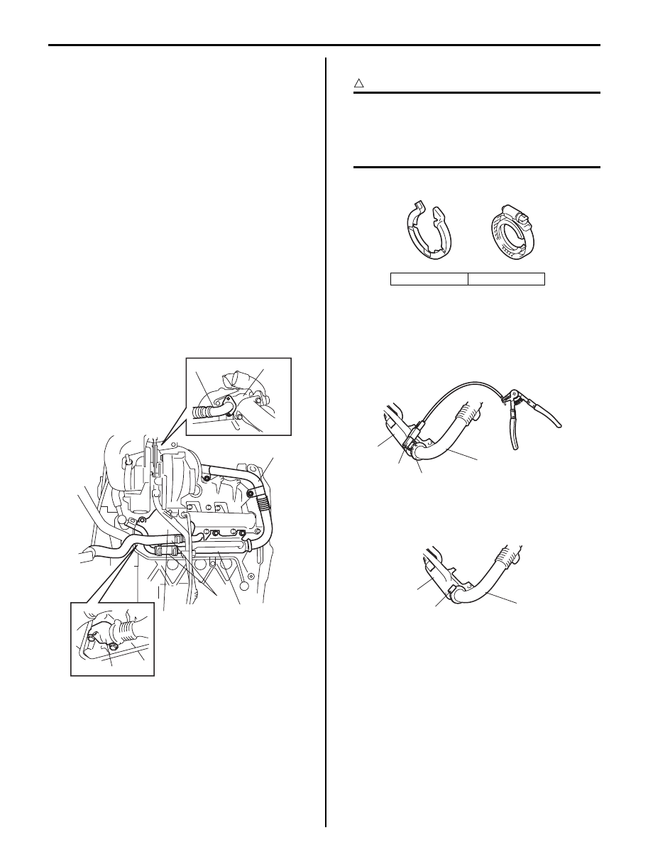
4) Disconnect water hoses (1) from EGR cooler (2).
5) Remove exhaust manifold heat shield (3) from 

exhaust manifold.

6) Disconnect EGR joint (4) from exhaust manifold.
7) Disconnect EGR pipe (5) from EGR valve (6).
8) Remove EGR cooler (2) with EGR pipe (5) and EGR 

joint (4) from cylinder block.

9) Remove EGR pipe as follows, if necessary.

CAUTION

!


EGR pipe clamp has two types as shown in 
figure. And, Type A is disposable one and it 
has not already been supplied.
Be sure to use Type B EGR pipe clamp after 
removing Type A EGR pipe clamp.


• For  Type  A

Remove EGR pipe (1) from EGR cooler (2) after 
removing EGR pipe clamp (3) with special tool.

Special tool
(A):  09910–68110 

• For  Type  B

Remove EGR pipe (1) from EGR cooler (2) after 
loosening EGR pipe clamp bolt (3).

5

1

3

5

6

2

4

I6JB0A143004-01

[A]: Type A

[B]: Type B

[A]

[B]

I5JB0B140146-01

(A)

1

3

2

I5JB0B140049-04

1

2

3

I5JB0B140148-01

Engine Mechanical: For F9Q Engine 1D-159

Installation

1) Install EGR cooler (1), EGR pipe (2) and EGR joint 

(3) with new gaskets.

Tightening torque
EGR cooler bolt (a):  25 N·m (2.5 kgf-m, 18.5 lb-ft)
EGR pipe bolt (b):  18 N·m (1.8 kgf-m, 13.0 lb-ft)
EGR pipe stiffener bolt (with washer) (c):  11 N·m 
(1.1 kgf-m, 8.0 lb-ft)
EGR pipe stiffener bolt (without washer) (c):  9 
N·m (0.9 kgf-m, 7.0 lb-ft)
EGR joint bolt (d):  25 N·m (2.5 kgf-m, 18.5 lb-ft)

2) Install EGR pipe as follows, if necessary.

• For  Type  A

Type A EGR pipe clamp is disposable one, install 
new Type B EGR pipe clamp as below-mentioned.

• For  Type  B

Install EGR pipe (1) to EGR cooler (2) by 
tightening EGR pipe clamp bolt as specified 
torque.

Tightening torque
Clamp bolt (a):  5 N·m (0.5 kgf-m, 4.0 lb-ft)

3) Install exhaust manifold heat shield (1) to exhaust 

manifold.

Tightening torque
Exhaust manifold heat shield bolt (a):  11 N·m (
1.1 kgf-m, 8.0 lb-ft)

4) Connect water hoses (2) to EGR cooler (3).

5) Install thermostat assembly referring to “Thermostat 

Assembly Removal and Installation: For Diesel 
Engine Model in Section 1F”
.

6) Install catalytic converter referring to “Exhaust 

System Components: For Diesel Engine Model in 
Section 1K”
.

7) Install engine assembly referring to “Engine 

Assembly Removal and Installation: For F9Q 
Engine”.

(a)

2

2

1

3

(c)

(d)

(b)

I6JB0A143005-01

1

2

(a)

I5JB0B140147-01

(a)

1

2

3

I5JB0B140051-01

1D-160 Engine Mechanical: For F9Q Engine

Turbocharger Components

S6JB0A1436056

CAUTION

!


Before starting engine (including when performing oil level check and air bleeding process of cooling 
system) for the first time after installing turbocharger, be sure to lubricate turbocharger, referring to 
“CAUTION” in “Installation” under “Turbocharger Assembly Removal and Installation”. Otherwise, 
lack of lubrication will cause turbocharger damage.


4

3

5

8

7

2

6

(i)

(c)

(d)

(e)

(b)

(f)

(g)

(h)

1

7

9

(h)

(h)

7

(c)

(a)

7

(a)

I6JB0A143006-02

1. Turbocharger assembly

: Do not disassemble.

8. Turbocharger inlet pipe

: 44 N

⋅m (4.4 kgf-m, 32.0 lb-ft)

2. Turbocharger lubrication pipe

9. Copper ring

: 25 N

⋅m (2.5 kgf-m, 18.0 lb-ft)

3. Oil return pipe No.1

: 2.5 N

⋅m (0.25 kgf-m, 2.0 lb-ft)

: 12 N

⋅m (1.2 kgf-m, 9.0 lb-ft)

4. Oil return pipe No.2

: 36 N

⋅m (3.6 kgf-m, 26.5 lb-ft)

: 16 N

⋅m (1.6 kgf-m, 12.0 lb-ft)

5. Turbocharger water inlet pipe

: 29 N

⋅m (2.9 kgf-m, 21.0 lb-ft)

: Do not reuse.

6. Turbocharger water outlet pipe

: 37 N

⋅m (3.7 kgf-m, 27.0 lb-ft)

7. Boost presser control solenoid valve

: 21 N

⋅m (2.1 kgf-m, 15.5 lb-ft)

Engine Mechanical: For F9Q Engine 1D-161

Turbocharger Assembly Removal and 
Installation

S6JB0A1436057

CAUTION

!


Never disassemble turbocharger assembly. 
Disassembly will spoil its original function. If 
faulty condition is found, replace it with new 
one.


Removal

1) Remove engine assembly referring to “Engine 

Assembly Removal and Installation: For F9Q 
Engine”.

2) Remove thermostat assembly referring to 

“Thermostat Assembly Removal and Installation: For 
Diesel Engine Model in Section 1F”.

3) Remove catalytic converter referring to “Exhaust 

System Components: For Diesel Engine Model in 
Section 1K”
.

4) Disconnect turbocharger outlet hose (1) from 

turbochanger (10).

5) Disconnect turbocharger water inlet hose (2) and 

outlet hose (3).

6) Remove exhaust manifold heat shield (4) from 

exhaust manifold.

7) Remove oil return pipe No.1 (5) and No.2 (6).
8) Disconnect turbocharger lubrication pipe (7) and 

lubrication pipe stiffeners from cylinder block.

9) Disconnect boost pressure control actuator hose (8) 

from boost pressure control actuator.

10) Loosen turbocharger inlet pipe bolt (9).

11) Remove turbocharger (10) from exhaust manifold.

12) Remove turbocharger inlet pipe (5) from 

turbocharger.

13) Remove turbocharger lubrication pipe (1), 

turbocharger lubrication pipe union nut (2), 
turbocharger water inlet pipe (3) and turbochanger 
water outlet pipe (4) from turbocharger, if necessary.

2

3

4

5

6

7

8

9

10

1

I6JB0A143007-01

1

2

3

4

5

I5JB0B140054-01


Content   ..  156  157  158  159   ..