Suzuki Grand Vitara JB416 / JB420 / JB419. Manual - part 143
 

  Index      Suzuki     Suzuki Grand Vitara JB416 / JB420 / JB419 - service repair manual 2007 year


Search            


Content   ..  141  142  143  144   ..


Suzuki Grand Vitara JB416 / JB420 / JB419. Manual - part 143


1D-98 Engine Mechanical: For J20 Engine

Camshaft journal

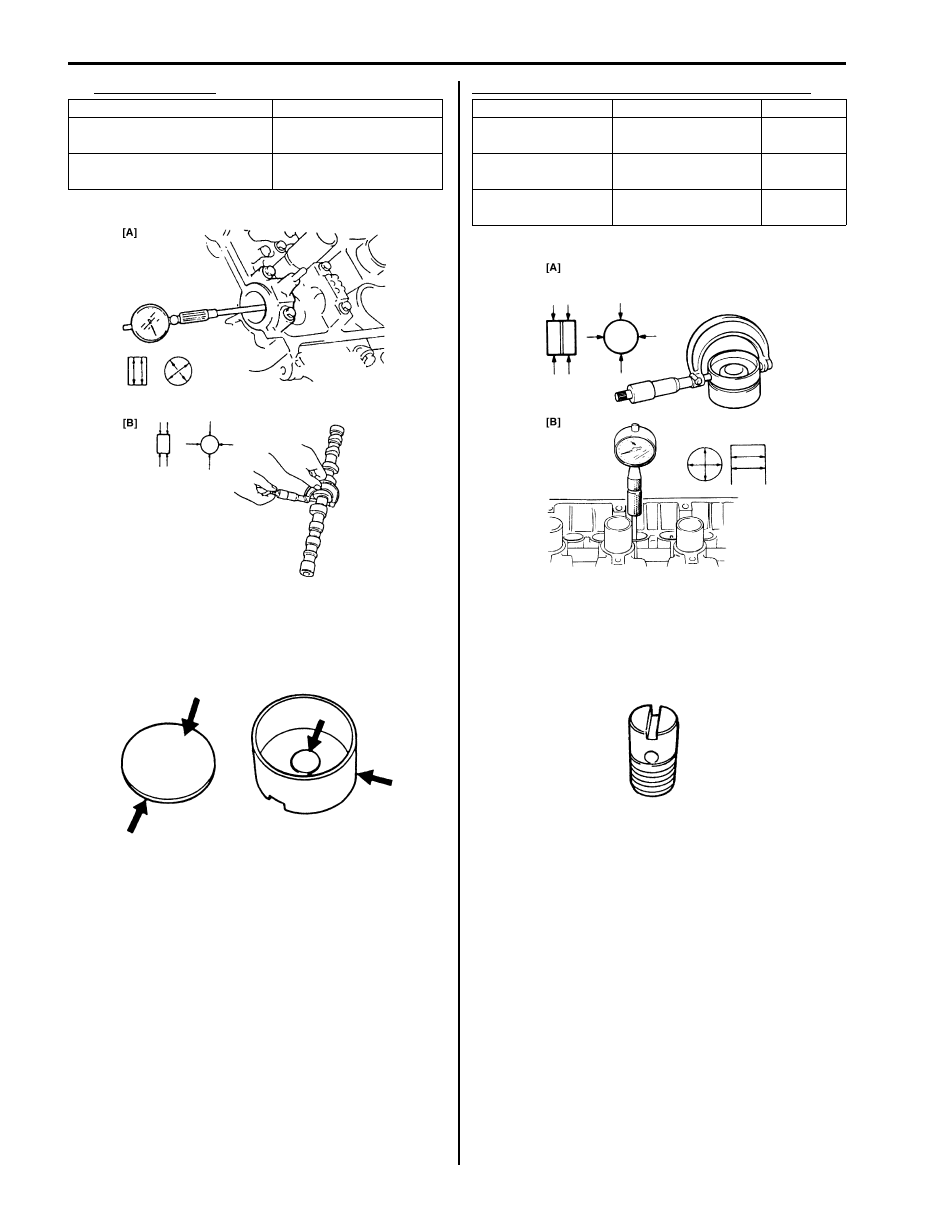
Wear of Tappet and Shim
Check tappet and shim for pitting, scratches, or damage.
If any malcondition is found, replace.

Measure cylinder head bore and tappet outside diameter 
to determine cylinder head-to-tappet clearance. If 
clearance exceeds limit, replace tappet or cylinder head.

Cylinder head bore and tappet outside diameter

Oil Relief Valve
Check oil relief valve for clogging and ball for being 
stuck.

Item

Standard

Camshaft journal bore 
diameter. (IN & EX) [A]

26.000 – 26.033 mm 
(1.0236 – 1.0249 in.)

Camshaft journal O.D. (IN & 
EX) [B]

25.959 – 25.980 mm 
(1.0221 – 1.0228 in.)

I5JB0A142036-01

I2RH0B140085-01

Item

Standard

Limit

Tappet outside 
diameter [A]

32.456 – 32.472 mm 

(1.2778 – 1.2784 in.)

Cylinder head bore 
[B]

32.500 – 32.525 mm 

(1.2795 – 1.2805 in.)

Cylinder head to 
tappet clearance

0.028 – 0.069 mm 

(0.0011 – 0.0027 in.)

0.15 mm 

(0.0059 in.)

I5JB0A142038-01

I2RH01140111-01

Engine Mechanical: For J20 Engine 1D-99

Valves and Cylinder Head Components

S6JB0A1426024

I5JB0A142039-01

1. Cylinder block

7. Valve stem seal

13. Cylinder head bolt (M6)

: Be sure to tighten cylinder head bolt (M8) after securing 
cylinder head bolt (M10).

2. Cylinder head

8. Valve spring

14. Knock pin

3. Cylinder head gasket

: Identification number provided on gasket comes 
to crankshaft pully side, facing up.

9. Valve spring retainer

: Tighten 52 N

⋅m (5.2 kgf-m, 38.0 lb-ft), 82 N⋅m (8.2 kgf-m, 59.5 

lb-ft), 0 N

⋅m (0 kgf-m, 0 lb-ft), 52 N⋅m (5.2 kgf-m, 38.0 lb-ft) 

and 103 N

⋅m (10.3 kgf-m, 74.5 lb-ft) by the specified 

procedure.

4. Intake valve

10. Valve cotter

: 11 N

⋅m (1.1 kgf-m, 8.0 lb-ft)

5. Exhaust valve

11. Valve guide

: Do not reuse.

6. Valve spring seat

12. Cylinder head bolt (M10)

: Apply engine oil to sliding surface of each part.

1D-100 Engine Mechanical: For J20 Engine

Valves and Cylinder Head Removal and 
Installation

S6JB0A1426025

Removal

1) Remove engine assembly from vehicle referring to 

“Engine Assembly Removal and Installation: For J20 
Engine”.

2) Remove oil pan referring to “Oil Pan and Oil Pump 

Strainer Removal and Installation: For J20 Engine in 
Section 1E”
.

3) Remove cylinder head cover referring to “Cylinder 

Head Cover Removal and Installation: For J20 
Engine”.

4) Remove timing chain cover. Refer to “Timing Chain 

Cover Removal and Installation: For J20 Engine” for 
removal.

5) Remove 2nd timing chain and 1st timing chain. Refer 

to “2nd Timing Chain and Chain Tensioner Removal 
and Installation: For J20 Engine” an
d “1st Timing 
Chain and Chain Tensioner Removal and 
Installation: For J20 Engine”
 for removal.

6) Remove camshafts, tappets and shims. Refer to 

“Camshafts, Tappet and Shim Removal and 
Installation: For J20 Engine”
 for removal.

7) Loosen cylinder head bolts (M10) in such order as 

numbered in figure and remove them.

NOTE
Don’t forget to remove cylinder head bolt 
(M6) (3) as shown in figure.


8) Check all around cylinder head for any other parts 

required to be removed or disconnected and remove 
or disconnect whatever necessary.

9) Remove cylinder head with intake manifold, exhaust 

manifold and water outlet cap. Use lifting device, if 
necessary.

Installation

1) Match match mark (1) on crank timing sprocket and 

mating surface (2) of cylinder block and lower 
crankcase.

2) Clean mating surface of cylinder head and cylinder 

block (2). Remove oil, old gasket and dust from 
mating surface.

3) Install knock pins (3) to cylinder block.
4) Install new cylinder head gasket (1) to cylinder block. 

Identification number (6) provided on gasket comes 
to crankshaft pulley side (4), facing up (toward 
cylinder head side).

1. Crankshaft pulley side

2. Flywheel side

“5”

“4”

“8”

“10”

“6”

“2”

3, “1”

“9”

“11”

“7”

“3”

1

2

I5JB0A142040-02

5. Flywheel side

I2RH01140118-01

I5JB0A142041-01

Engine Mechanical: For J20 Engine 1D-101

5) Install cylinder head to cylinder block.

Apply engine oil to cylinder head bolts and tighten 
them gradually as follows.
a) Tighten cylinder head bolts (M10) to 52 N

⋅m (5.2 

kgf-m, 38.0 lb-ft) according to numerical order in 
figure.

b) In the same manner as in step a), retighten 

cylinder head bolts (M10) to 82 N

⋅m (8.2 kgf-m, 

59.5 lb-ft).

c) Loosen cylinder head bolts (M10) until tightening 

torque is reduced to 0 according to numerical 
order in figure.

d) Tighten cylinder head bolts (M10) to 52 N

⋅m (5.2 

kgf-m, 38.0 lb-ft) according to numerical order in 
figure.

e) In the same manner as in step b), retighten 

cylinder head bolts (M10) to 103 N

⋅m (10.3 kgf-

m, 74.5 lb-ft).

f) Tighten cylinder head bolt (M6) to specified 

torque.

Tightening torque
Cylinder head bolt (M10) (a):  Tighten 52 N

(5.2 kgf-m, 38.0 lb-ft), 82 N

m (8.2 kgf-m, 59.5 

lb-ft), 0 N

m (0 kgf-m, 0 lb-ft), 52 Nm (5.2 kgf-

m, 38.0 lb-ft) and 103 N

m (10.3 kgf-m, 74.5 lb-

ft) by the specified procedure.
Cylinder head bolt (M6) (b):  11 N·m (1.1 kgf-
m, 8.0 lb-ft)

6) Install camshafts and tappets and shims. Refer to 

“Camshafts, Tappet and Shim Removal and 
Installation: For J20 Engine” for
 installation.

7) Install 1st timing chain. Refer to “1st Timing Chain 

and Chain Tensioner Removal and Installation: For 
J20 Engine” fo
r installation.

8) Install 2nd timing chain. Refer to “2nd Timing Chain 

and Chain Tensioner Removal and Installation: For 
J20 Engine” fo
r installation.

9) Install timing chain cover. Refer to “Timing Chain 

Cover Removal and Installation: For J20 Engine” for 
installation.

10) Check intake and exhaust valve lashes referring to 

“Valve Lash (Clearance) Inspection: For J20 
Engine”.

11) Install cylinder head cover referring to “Cylinder 

Head Cover Removal and Installation: For J20 
Engine”.

12) Install oil pan referring to “Oil Pan and Oil Pump 

Strainer Removal and Installation: For J20 Engine in 
Section 1E”
.

13) Install engine assembly to vehicle referring to 

“Engine Assembly Removal and Installation: For J20 
Engine”.

1. Crankshaft pulley side

2. Flywheel side

1. Crankshaft pulley side

2. Flywheel side

“7”

“9”

“4”

“2”

“6”

“8”

“5”

“1”

“3”

“10”

1

2

I5JB0A142042-01

“4”

“3”

“7”

“9”

“5”

“1”

“8”

“10”

“6”

“2”

1

2

I5JB0A142043-01

1. Crankshaft pulley side

2. Flywheel side

“7”, (a)

“9”, (a) 3, “11”, (b) “4”, (a)

“2”, (a)

“6”, (a)

“8”, (a)

“5”, (a)

“1”, (a)

“3”, (a)

“10”, (a)

I5JB0A142044-02


Content   ..  141  142  143  144   ..