Suzuki Grand Vitara JB416 / JB420 / JB419. Manual - part 80
 

  Index      Suzuki     Suzuki Grand Vitara JB416 / JB420 / JB419 - service repair manual 2007 year


Search            


Content   ..  78  79  80  81   ..


Suzuki Grand Vitara JB416 / JB420 / JB419. Manual - part 80


1A-267 Engine General Information and Diagnosis: For Diesel Engine Model

General Description

Statement on Cleanliness and Care

S6JB0A1121007

An automobile engine is a combination of many 
machined, honed, polished and lapped surfaces with 
tolerances that are measured in the thousands of an 
millimeter (ten thousands of inch).
Accordingly, when any internal engine parts are 
serviced, care and cleanliness are important.
It should be understood that proper cleaning and 
protection of machined surfaces and friction areas is part 
of the repair procedure. This is considered standard 
shop practice even if not specifically stated.
• A liberal coating of engine oil should be applied to 

friction areas during assembly to protect and lubricate 
the surfaces on initial operation.

• Whenever valve train components, pistons, piston 

rings, connecting rods, rod bearings, and crankshaft 
journal bearings are removed for service, they should 
be retained in order.
At the time of installation, they should be installed in 
the same locations and with the same mating 
surfaces as when removed.

• Battery cables should be disconnected before any 

major work is performed on the engine.
Failure to disconnect cables may result in damage to 
wire harness or other electrical parts.

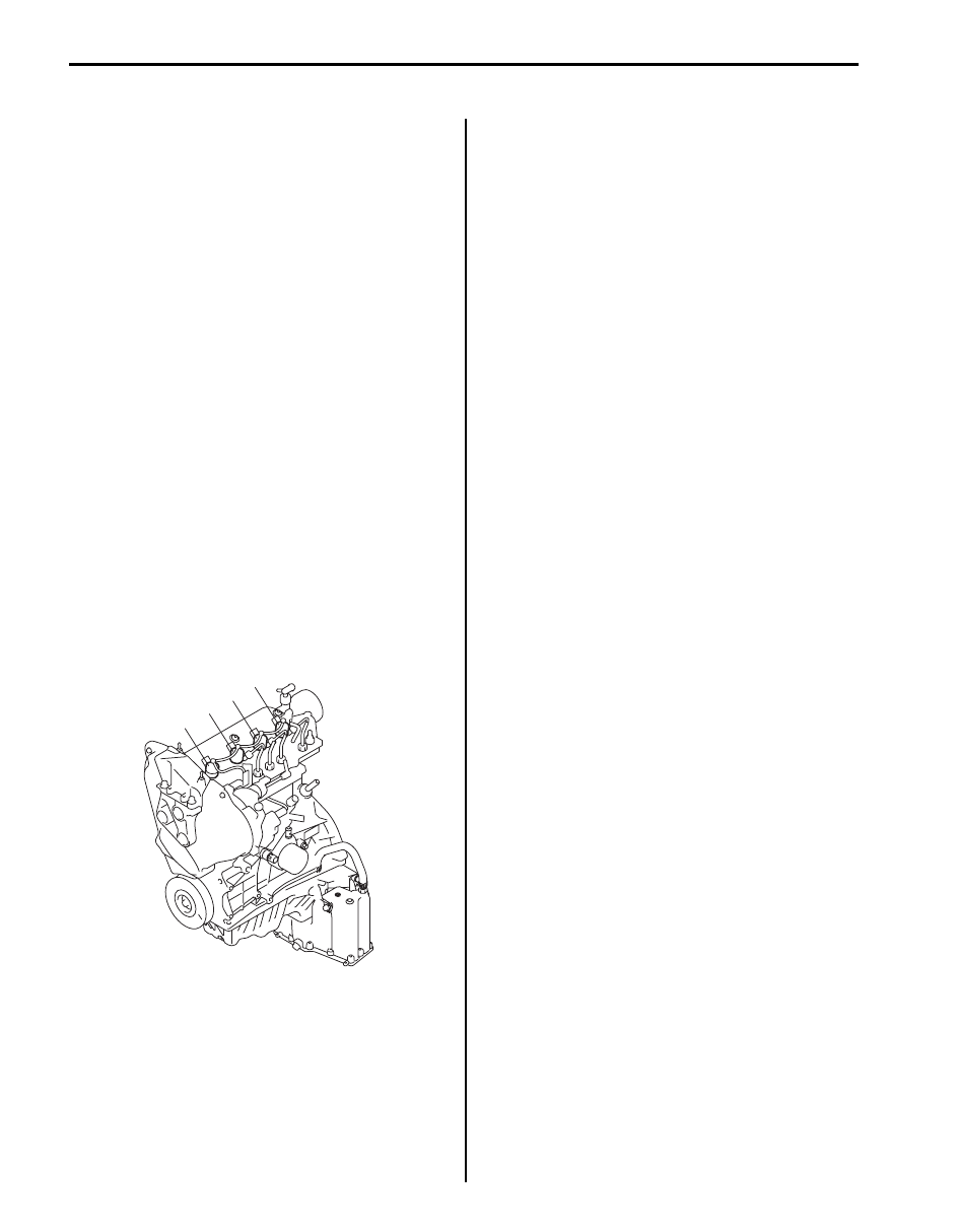
• The four cylinders of the engine are identified by 

numbers; No.1 (1), No.2 (2), No.3 (3) and No.4 (4) as 
counted from flywheel side to crankshaft pulley side.

Engine Diagnosis General Description

S6JB0A1121002

The engine and emission control system in this vehicle 
are controlled by ECM. ECM has an On-Board 
Diagnostic system which detects a malfunction in this 
system and abnormality of those parts that influence the 
engine exhaust emission. When diagnosing engine 
troubles, be sure to have full understanding of the outline 
of “On-Board Diagnostic System Description: For Diesel 
Engine Model” a
nd each item in “Precautions in 
Diagnosing Trouble: For Diesel Engine Model” 
and 
execute diagnosis according to “Engine and Emission 
Control System Check: For Diesel Engine Model”.
There is a close relationship between the engine 
mechanical, engine cooling system, exhaust system, 
etc. and the engine and emission control system in their 
structure and operation. In case of an engine trouble, 
even when the warning light (MIL, injection warning light, 
and/or red stop warning light) doesn’t turn ON, it should 
be diagnosed according to this flow table.

On-Board Diagnostic System Description

S6JB0A1121003

ECM in this vehicle has the following functions.
• When the ignition switch is turned ON with the engine 

at a stop, MIL (1), turns ON to check the warning light 
and its circuit.

• When ECM detects a malfunction, it makes injection 

warning light (gravity 1 fault) (2) and/or red stop 
warning light (gravity 2 fault) (3) in the meter cluster of 
the instrument panel turn ON and stores the 
malfunction area in its memory.

• When ECM detects a malfunction which gives an 

adverse effect to vehicle emission while the engine is 
running, it makes the malfunction indicator lamp in the 
meter cluster of the instrument panel turn ON and 
stores the malfunction area in its memory.

1

2

3

4

I5JB0B110001-01

Engine General Information and Diagnosis: For Diesel Engine Model 1A-268

• When a malfunction is detected, a malfunction in 

some areas in the system and driving cycles then are 
stored in ECM memory (For the details, refer to 
description on “Indicator Light Operation Table: For 
Diesel Engine Model”.

Warm-Up Cycle
A “warm-up cycle” means sufficient vehicle operation 
such that the coolant temperature has risen by at least 
22 

°C (40 °F) from engine starting and reaches a 

minimum temperature of 70 

°C (160 °F).

Driving Cycle
A “driving cycle” consists of two parts, engine startup 
and engine shutoff. 

3 Driving Cycle Detection Logic
The malfunction detected in the first driving cycle is 
stored in ECM memory (in the form of pending DTC) but 
the malfunction indicator lamp does not light at this time. 
It does not light up at the second detection of same 
malfunction also in the next driving cycle. It lights up at 
the third detection of same malfunction also in the third 
driving cycle.

Pending Diagnostic Trouble Code (DTC)
Pending DTC means a DTC detected and stored 
temporarily at first or second driving cycle of the DTC 
which is detected in the 3 driving cycle detection logic.

Data Link Connector (DLC)
DLC (1) is in compliance with SAE J1962 in its 
installation position, the shape of connector and pin 
assignment. 
K line (3) of ISO 9141 is used for SUZUKI scan tool or 
OBD generic scan tool to communicate with ECM, Air 
bag SDM, immobilizer control module, BCM (Body 
electrical Control Module), 4WD control module and 
ABS or ESP

® control module.

1

3

2

I5JB0B110002-01

2. B+

4. ECM ground

5. Body ground

2

3

4

5

1

9

10

11

12

13

14

15

16

1

2

3

4

5

6

7

8

1

I5JB0A110004-01

1A-269 Engine General Information and Diagnosis: For Diesel Engine Model

CAN Communication System Description

S6JB0A1121005

ECM (1), ABS or ESP

® control module (2), BCM (3), 4WD control module (4), keyless start control module (5) 

combination meter (6), immobilizer control module (7) and steering angle sensor (8) (ESP

® model) of this vehicle 

communicate control data between each control module.
Communication of each control module is established by CAN (Controller Area Network) communication system.

CAN communication system uses the serial communication in which data is transmitted at a high speed. It uses a 
twisted pair of two communication lines for the high-speed data transmission. As one of its characteristics, multiple 
control modules can communicate simultaneously. In addition, it has a function to detect a communication error 
automatically. Each module reads necessary data from the received data and transmits data. ECM communicates 
control data with each control module as follows.

1

3

4

5

7

8

2

6

I6JB01110110-02

Engine General Information and Diagnosis: For Diesel Engine Model 1A-270

ECM Transmission Data

NOTE

• In communication between ECM and combination meter, between ECM and 4WD control module, 

between ECM and keyless start control module, data is transmitted only from ECM to combination 
meter and 4WD control module. (combination meter and 4WD control module does not transmit data 
to ECM.)

• For vehicle without diesel particulate filter, data with asterisk (*) below are not applicable.


ECM Reception Data

Engine torque signal

Accelerator position

Engine speed signal

MIL control signal

Injection warning light control signal

(Gravity 1 Fault)

Red stop warning light control signal

(Gravity 2 Fault)

Glow indicator light control signal

Diesel particulate filter warning light

control signal*

Fuel filter warning light control signal

Engine coolant temperature signal

Cruise control signal

“CRUISE” and “SET” indicator light

control signal

Vehicle speed signal

Fuel consumption signal

Brake pedal switch signal

A/C compressor clutch

A/C refrigerant pressure signal

Additional heater relay signal

Radiator cooling fan relay signal

BCM

Transmits data

of ECM

4WD control

module

Combination 

meter

ESP® control 

module

ABS control

module

Keyless start

control

module

I6JB0A112001-05

BCM

ESP® control

module

A/C switch ON signal 

Torque up request

Torque reduction request

Wheel speed pulse (rear right)

Wheel speed pulse (rear left)

ABS active

ESP® status signal

ABS control

module

Transmits data of ECM

I6JB0A112002-05


Content   ..  78  79  80  81   ..