Suzuki Grand Vitara JB416 / JB420 / JB419. Manual - part 57
 

  Index      Suzuki     Suzuki Grand Vitara JB416 / JB420 / JB419 - service repair manual 2007 year


Search            


Content   ..  55  56  57  58   ..


Suzuki Grand Vitara JB416 / JB420 / JB419. Manual - part 57


1A-175 Engine General Information and Diagnosis: For Petrol Engine Model

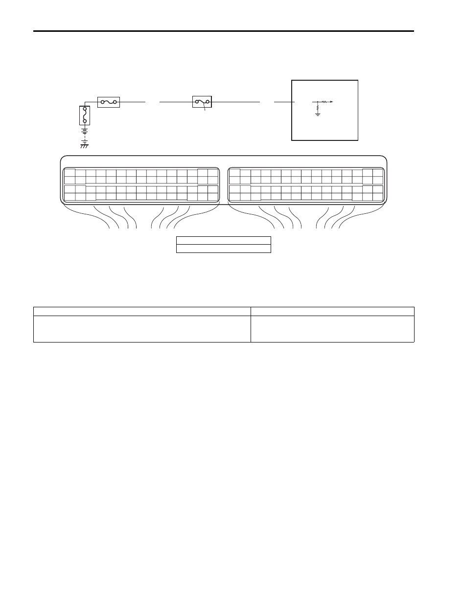
DTC P1510: ECM Back-Up Power Supply Malfunction

S6JB0A1114062

Wiring Diagram

Circuit Description
Battery voltage is supplied so that DTC memory, values for engine control learned by ECM, etc. are kept in ECM even 
when the ignition switch is turned OFF.

DTC Detecting Condition and Trouble Area

DTC Confirmation Procedure

1) Connect scan tool to DLC with ignition switch turned OFF.
2) Turn ON ignition switch and clear DTC using scan tool and run engine at idle speed for 1 min.
3) Check DTC and pending DTC.

E23

C37

3

4

18

19

5

6

7

10

11

17

20

47

46

49

50

51

21

22

52

16

25

9

24

14
29

55

57

54 53

59

60

58

2

26

27

28

15
30

56

48

32

31

34

35

36

37

40

42

39 38

44

45

43

41

33

1

12

13

23

8

3

4

18

19

5

6

7

10

11

17

20

47

46

49

50

51

21

22

52

16

25

9

24

14
29

55

57

54 53

59

60

58

2

26

27

28

15
30

56

48

32

31

34

35

36

37

40

42

39 38

44

45

43

41

33

1

12

13

23

8

2

1

E23-2  

WHT

WHT

I5JB0A110066-01

1. ECM
2. “DOME” fuse

DTC detecting condition

Trouble area

Back-up power circuit voltage is no inputted for 5 seconds 
continuously while engine is running.
(1 driving cycle detection logic)

Battery voltage supply circuit

Engine General Information and Diagnosis: For Petrol Engine Model 1A-176

DTC Troubleshooting

NOTE
Before this trouble shooting is performed, read the precautions for DTC troubleshooting referring to 
“Precautions for DTC Troubleshooting: For Petrol Engine Model”.


DTC P1603: TCM Trouble Code Detected (For J20 Engine)

S6JB0A1114063

Wiring Diagram

Step

Action

Yes

No

1

Was “Engine and Emission Control System Check” 
performed?

Go to Step 2.

Go to “Engine and 
Emission Control 
System Check: For 
Petrol Engine Model”.

2

Battery voltage supply circuit check
1) Turn OFF ignition switch.
2) Remove ECM from its bracket with ECM connectors 

connected.

3) With engine running, measure voltage between “E23-2” 

terminal of ECM connector and engine ground.

Is voltage 10 – 14 V?

Poor “E23-2” 
connection or 
intermittent trouble.
Check for intermittent 
referring to “Intermittent 
and Poor Connection 
Inspection in Section 
00”.
If wire and connections 
are OK, substitute a 
known-good ECM and 
recheck.

“DOME” fuse blown, 
“WHT” wire is circuit 
open or short circuit.

WHT/BLU

WHT/RED

E23

C37

3

4

18

19

5

6

7

10

11

17

20

47

46

49

50

51

21

22

52

16

25

9

24

14
29

55

57

54 53

59

60

58

2

26

27

28

15
30

56

48

32

31

34

35

36

37

40

42

39 38

44

45

43

41

33

1

12

13

23

8

3

4

18

19

5

6

7

10

11

17

20

47

46

49

50

51

21

22

52

16

25

9

24

14
29

55

57

54 53

59

60

58

2

26

27

28

15
30

56

48

32

31

34

35

36

37

40

42

39 38

44

45

43

41

33

1

12

13

23

8

E23-4

E23-19

1

RED

WHT

E03-12

E03-6

WHT/BLU

WHT/RED

E03-8

E03-10

RED

WHT

E92-7

E92-17

2

3

I5JB0A110067-02

1. ECM

2. TCM (for A/T model)

3. ABS / ESP

® control module

1A-177 Engine General Information and Diagnosis: For Petrol Engine Model

DTC Detecting Condition
When ECM receives a trouble code from TCM, which indicates that some problem occurred in sensor circuits and its 
calculated values used for operations such as idle speed control, engine power control, and so on by TCM, ECM sets 
DTC P1603. (TCM outputs the trouble code to ECM when TCM can not compute the engine control signal due to 
malfunctions of sensor circuits used for gear shift control.)

DTC Troubleshooting

NOTE
Before this trouble shooting is performed, read the precautions for DTC troubleshooting referring to 
“Precautions for DTC Troubleshooting: For Petrol Engine Model”.


Step

Action

Yes

No

1

Was “Engine and Emission Control System Check” 
performed?

Go to Step 2.

Go to “Engine and 
Emission Control 
System Check: For 
Petrol Engine Model”
.

2

DTC check
1) Check DTC of TCM referring to “DTC Check in Section 

5A”.

Is there any DTC(s)?

Go to applicable DTC 
diag. flow.

Substitute a known-
good ECM and recheck.

Engine General Information and Diagnosis: For Petrol Engine Model 1A-178

DTC P1674: CAN Communication (Bus Off Error)

S6JB0A1114064

Wiring Diagram

WHT

RED

WHT

RED

G44-18

G44-19

G44

[A]

[B]

[C]

[H]

[G]

1

2

3

4

5

6

7

8

9

10

11

14

15

16
36

34 33 32

30 29

24 23

37

18

19

20

WHT/BLU

WHT/BLU

WHT/RED

WHT/RED E23-4

E23-19

WHT

RED

WHT

RED

E92-17

E92-7

WHT

RED

E91-22
E91-23

WHT

RED

RED

G31-1
G31-3

G31-4

6

5

16 15 14 13 12 11

4 3

24 23

21

22

10 9

8

7

2

1

19

20

18 17

E92

E23

1

2

3

4

5

6

7

8

9

10

11

17

1615141312

2221201918

G28

[F]

G31

E91

1

2

3

4

7

8

9

10

11

14

15

16
36

34

35

24 23

21

22

28 27

25

26

37

39 38

40

18 17

13 12

19

20

1

2

3

10

11

12

16

17

18

15 14 13

19

20

21

25

26

5

6

[I]

E53

[E]

E03

15
16
17
18
19
20
21
22
23
24
25

2
3
4
5
6
7
8
9

10
11
12

1

13

14

26

G31-2

WHT

1

2

3

4

9

5

6

8

7

[K]

E03-12

E03-10

E03-6

E03-8

10

11

[L]

E53-13

E53-42

E53-44

E53-46

17

18

19

20

21

22

23

24

25

26

27

28

29

30

31

33

34

35

36

37

38

39

40

32

1

2

3

4

5

6

7

8

9

10

11

12

13

14

15

16

[D]

8 7

6 5 4 3

2 1

9

10

11

12

13

14

15

16

16

1

15

2

3

4

5

6

7

8

9

10

11

12

13

14

17

18

19

20

21

22

23

24

25

26

27

28

29

30

31

32

33

34

35

36

37

38

39

40

41

42

43

44

45

46

47

[J]

G45

10 9

3 2 1

WHT

RED

G45-9
G45-10

G28-8

G28-10

I5JB0D110007-01

[A]: Keyless start control module connector (if equipped) (viewed from harness side)

1. BCM

[B]: ECM connector (viewed from harness side)

2. 4WD control module (if equipped)

[C]: TCM connector (for A/T model) (viewed from harness side)

3. TCM (for A/T model)

[D]: DLC (viewed from terminal side)

4. Keyless start control module (if equipped)

[E]: ABS hydraulic unit / control module connector (viewed from terminal side) 

5. DLC

[F]: Combination meter connector (viewed from harness side)

6. ECM

[G]: 4WD control module connector (viewed from harness side)

7. ABS hydraulic unit / control module assembly

[H]: BCM connector (viewed from harness side) 

8. Combination meter

[I]: ESP

® control module connector (viewed from harness side)

9. CAN circuit junction connector

[J]: Steering angle sensor connector (viewed from harness side) 

10. ESP

® control module

[K]: Vehicle without ESP

®

11. Steering angle sensor (for vehicle with ESP

®)

[L]: Vehicle with ESP

®


Content   ..  55  56  57  58   ..