Suzuki Grand Vitara JB416 / JB420 / JB419. Manual - part 50
 

  Index      Suzuki     Suzuki Grand Vitara JB416 / JB420 / JB419 - service repair manual 2007 year


Search            


Content   ..  48  49  50  51   ..


Suzuki Grand Vitara JB416 / JB420 / JB419. Manual - part 50


1A-147 Engine General Information and Diagnosis: For Petrol Engine Model

1) With ignition switch OFF, connect scan tool to DLC.
2) Turn ON ignition switch and clear DTC using scan tool.
3) Start engine and warm up normal operating temperature.
4) Drive vehicle at more than 40 km/h, 25 mph for 5 min. or more.
5) Check DTC and pending DTC.

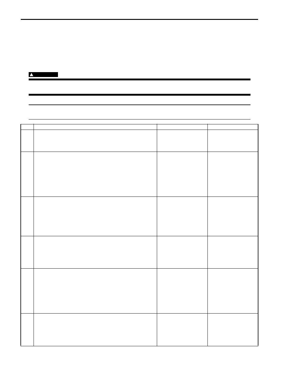
DTC Troubleshooting

WARNING

!


In order to reduce risk of fire and personal injury, this work must be performed in a well ventilated area 
and away from any open flames such as gas water heater.


NOTE
Before this trouble shooting is performed, read the precautions for DTC troubleshooting referring to 
“Precautions for DTC Troubleshooting: For Petrol Engine Model”.


Step

Action

Yes

No

1

Was “Engine and Emission Control System Check” 
performed?

Go to Step 2.

Go to “Engine and 
Emission Control 
System Check: For 
Petrol Engine Model”
.

2

EVAP canister purge power supply circuit check
1) Turn OFF ignition switch and disconnect connector from 

EVAP canister purge valve.

2) Measure voltage between engine ground and “BLU/

BLK” wire terminal of EVAP canister purge valve 
connector with ignition switch turned ON.

Is it voltage 10 – 14 V?

Go to Step 3.

“BLU/BLK” wire is open 
circuit.

3

Wire circuit check
1) Disconnect connectors from ECM with ignition switch 

turned OFF.

2) Measure resistance between “C37-13” terminal of ECM 

connector and vehicle body ground.

Is resistance infinity?

Go to Step 4.

“GRN/BLK” wire is 
shorted to ground 
circuit.

4

Wire circuit check
1) Measure voltage between “C37-13” terminal of ECM 

connector and vehicle body ground with ignition switch 
turned ON.

Is voltage 0 V?

Go to Step 5.

“GRN/BLK” wire is 
shorted to other circuit.

5

Wire circuit check
1) Connect connector to purge control valve with ignition 

switch turned OFF.

2) Turn ON ignition switch and measure voltage between 

“C37-13” terminal of ECM connector and vehicle body 
ground.

Is it voltage 10 – 14 V?

Go to Step 6.

“GRN/BLK” wire is open 
circuit.

6

EVAP canister purge control valve check
1) Check EVAP canister purge control valve referring to 

“EVAP Canister Purge Valve Inspection: For Petrol 
Engine Model in Section 1B”
.

Is it in good condition?

Go to Step 7.

Faulty EVAP canister 
purge control valve.

Engine General Information and Diagnosis: For Petrol Engine Model 1A-148

DTC P0462: Fuel Level Sensor Circuit Low

S6JB0A1114048

Wiring Diagram 

DTC Detecting Condition and Trouble Area

DTC Confirmation Procedure

1) With ignition switch turned OFF, connect scan tool.
2) Turn ON ignition switch and clear DTC using scan tool.
3) Start engine and run it for 30 sec. or more.
4) Check DTC and pending DTC.

7

EVAP canister purge control circuit check
1) With ignition switch turn OFF, measure resistance 

between “E23-1/16” terminal and “C37-13” terminal of 
ECM connector.

Is resistance below 40 

 at 20 

°

C, 68 

°

F?

Faulty ECM. Substitute 
a known-good ECM and 
recheck.

“GRN/BLK” and/or 
“BLU/BLK” wire are high 
resistance circuit.

Step

Action

Yes

No

E23

C37

3

4

18

19

5

6

7

10

11

17

20

47

46

49

50

51

21

22

52

16

25

9

24

14
29

55

57

54 53

59

60

58

2

26

27

28

15
30

56

48

32

31

34

35

36

37

40

42

39 38

44

45

43

41

33

1

12

13

23

8

3

4

18

19

5

6

7

10

11

17

20

47

46

49

50

51

21

22

52

16

25

9

24

14
29

55

57

54 53

59

60

58

2

26

27

28

15
30

56

48

32

31

34

35

36

37

40

42

39 38

44

45

43

41

33

1

12

13

23

8

12 V

1

5

E23-24

YEL/RED

BLK/YEL

YEL/GRN

PNK

BLK

WHT/GRN

E23-15

BLK/WHT

BLU/BLK

BLU/BLK

BLU/BLK

WHT/GRN

BLK/RED

BLK/RED

BLK/RED

BLK/YEL

BLU

12V

5V

6

7

4

3

2

E23-1  

E23-60  

E23-16  

BLU/BLK

I5JB0A110055-02

1. Fuel pump assembly

4. Sub fuel level sensor

7. Fuel pump relay

2. Fuel pump

5. ECM

3. Main fuel level sensor

6. Main relay

DTC detecting condition

Trouble area

Fuel level sensor voltage is lower than 0.5 V for 3 seconds 
continuously.
(1 driving cycle detection logic but MIL does not light up)

• ECM power and/or ground circuit malfunction
• ECM malfunction
• Fuel level sensor and/or its circuit malfunction

1A-149 Engine General Information and Diagnosis: For Petrol Engine Model

DTC Troubleshooting

NOTE
Before this trouble shooting is performed, read the precautions for DTC troubleshooting referring to 
“Precautions for DTC Troubleshooting: For Petrol Engine Model”.


Step

Action

Yes

No

1

Was “Engine and Emission Control System Check” 
performed?

Go to Step 2.

Go to “Engine and 
Emission Control 
System Check: For 
Petrol Engine Model”
.

2

Do you have SUZUKI scan tool?

Go to Step 3.

Go to Step 4.

3

Fuel level sensor output signal check with SUZUKI scan 
tool
1) Connect SUZUKI scan tool to DLC with ignition switch 

turned OFF.

2) Turn ON ignition switch and check fuel level displayed 

on SUZUKI scan tool.

Is 100% displayed?

Go to Step 5.

Intermittent trouble. 
Check for intermittent 
referring to “Intermittent 
and Poor Connection 
Inspection in Section 
00”.

4

Fuel level sensor output signal check
1) Turn OFF ignition switch.
2) Remove ECM from its bracket with ECM connector 

connected.

3) Turn ON ignition switch and measure voltage between 

“E23-24” terminal of ECM connector and vehicle body 
ground.

Is voltage about 3.5 V or less?

Go to Step 5.

Intermittent trouble. 
Check for intermittent 
referring to “Intermittent 
and Poor Connection 
Inspection in Section 
00”.

5

Fuel level sensor output signal circuit check
1) Disconnect fuel pump connector referring to “Fuel Tank 

Removal and Installation: For Petrol Engine Model in 
Section 1G”.

2) Disconnect connectors from ECM with ignition switch 

turned OFF.

3) Measure resistance between “E23-24” terminal of ECM 

connector and vehicle body ground.

Is resistance infinity?

Go to Step 6.

“YEL/RED” wire is 
shorted to ground 
circuit.

6

Fuel level sensor output signal circuit check
1) Connect connectors to ECM.
2) Measure voltage between “E23-24” terminal of ECM 

connector and engine ground with ignition switch turned 
ON.

Is voltage 10 – 14 V?

Go to Step 7.

Substitute a known-
good ECM and recheck.

7

Fuel level sensor check
1) Check fuel level sensor (main and sub) referring to “Fuel 

Level Sensor Inspection in Section 9C”

Is it in good condition?

“YEL/GRN” wire 
between main fuel lever 
sensor and sub fuel 
level sensor is shorted 
to ground circuit. If wire 
is OK, substitute a 
known-good ECM and 
recheck.

Faulty fuel level sensor.

Engine General Information and Diagnosis: For Petrol Engine Model 1A-150

DTC P0463: Fuel Level Sensor Circuit High

S6JB0A1114049

Wiring Diagram 
Refer to “DTC P0462: Fuel Level Sensor Circuit Low: For Petrol Engine Model”.

DTC Detecting Condition and Trouble Area

DTC Confirmation Procedure

1) With ignition switch turned OFF, connect scan tool.
2) Turn ON ignition switch and clear DTC using scan tool.
3) Start engine and run it for 30 sec. or more.
4) Check DTC and pending DTC.

DTC Troubleshooting

NOTE
Before this trouble shooting is performed, read the precautions for DTC troubleshooting referring to 
“Precautions for DTC Troubleshooting: For Petrol Engine Model”.


DTC detecting condition

Trouble area

Fuel level sensor voltage is higher than 4.9 V for 3 seconds 
continuously.
(1 driving cycle detection logic but MIL does not light up)

• ECM power and/or ground circuit malfunction
• ECM malfunction
• Fuel level sensor and/or its circuit malfunction

Step

Action

Yes

No

1

Was “Engine and Emission Control System Check” 
performed?

Go to Step 2.

Go to “Engine and 
Emission Control 
System Check: For 
Petrol Engine Model”.

2

Does fuel level meter in combination meter indicate “E” 
(empty)?

Replenish fuel tank with 
fuel and go to Step 3.

Go to Step 3.

3

Do you have SUZUKI scan tool?

Go to Step 4.

Go to Step 5.

4

Fuel level sensor output signal check with SUZUKI scan 
tool
1) Connect SUZUKI scan tool to DLC with ignition switch 

turned OFF.

2) Turn ON ignition switch and check fuel level displayed 

on SUZUKI scan tool.

Is it 3% or less?

Go to Step 6.

Intermittent trouble. 
Check for intermittent 
referring to “Intermittent 
and Poor Connection 
Inspection in Section 
00”.

5

Fuel level sensor output signal check
1) Turn OFF ignition switch.
2) Remove ECM from its bracket with ECM connectors 

connected.

3) Turn ON ignition switch and measure voltage between 

“E23-24” terminal of ECM connector and vehicle body 
ground.

Is voltage about 3.5 V or more?

Go to Step 6.

Intermittent trouble. 
Check for intermittent 
referring to “Intermittent 
and Poor Connection 
Inspection in Section 
00”.

6

Fuel level sensor circuit resistance check
1) Disconnect connectors from ECM with ignition switch 

turned OFF.

2) Check for proper connection to “E23-24” terminal of 

ECM connector.

3) If OK, measure resistance between “E23-24” terminal of 

ECM connector and vehicle body ground.

Is resistance below 280 

?

Go to Step 7.

Go to Step 8.


Content   ..  48  49  50  51   ..