Suzuki Grand Vitara JB416 / JB420 / JB419. Manual - part 32
1A-75 Engine General Information and Diagnosis: For Petrol Engine Model
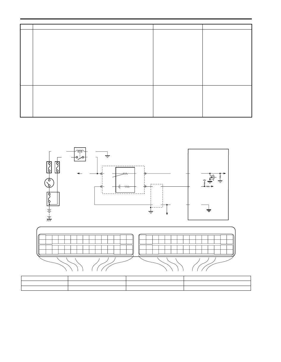
DTC P0037 / P0038: HO2S Heater Control Circuit Low / High (Sensor-2)
S6JB0A1114017
Wiring Diagram
10 A/F sensor heater control circuit check
1) Disconnect connector from ECM with ignition switch
turned OFF.
2) Check for proper connection of A/F sensor heater circuit
terminal to ECM connector.
3) If connection are OK, measure each wire resistance of
sensor heater control circuit at ECM connector between
ECM to A/F sensor and ECM to vehicle body ground.
Is each measured wire resistance lower than 1
Ω
?
Go to Step 11.
Repair or replace
defective wire circuit.
11 A/F sensor heater circuit check
1) Measure insulation resistance between control terminal
of A/F sensor heater and ground terminal of A/F sensor
heater at ECM connector.
Is measured resistance infinity?
Substitute a known
good ECM and recheck.
Repair or replace short
wire.
Step
Action
Yes
No
E23
C37
3
4
18
19
5
6
7
10
11
17
20
47
46
49
50
51
21
22
52
16
25
9
24
14
29
55
57
54 53
59
60
58
2
26
27
28
15
30
56
48
32
31
34
35
36
37
40
42
39 38
44
45
43
41
33
1
12
13
23
8
3
4
18
19
5
6
7
10
11
17
20
47
46
49
50
51
21
22
52
16
25
9
24
14
29
55
57
54 53
59
60
58
2
26
27
28
15
30
56
48
32
31
34
35
36
37
40
42
39 38
44
45
43
41
33
1
12
13
23
8
4
3
9
RED
GRN
PNK
BLK
C37-47
C37-11
C37-57
6
2
7
10
BLK
BLU
WHT
BLK/RED
GRY/GRN
1
8
5
5V
BLK/WHT
BLK
PNK
*GRN
I5JB0A110032-01
1. HO2S heater relay
4. “O2 HTR” fuse
7. Heater
10. To other sensors
2. Shield wire
5. “IG COIL” fuse
8. To A/F sensor heater
*: For M16 engine
3. Ignition switch
6. HO2S-2
9. ECM