Suzuki Grand Vitara JB419. Manual - part 130
 

  Index      Suzuki     Suzuki Grand Vitara JB419 (with F9Q engine) - service repair manual 2007 year


Search            


Content   ..  128  129  130  131   ..


Suzuki Grand Vitara JB419. Manual - part 130


Air Conditioning System:  7B-26

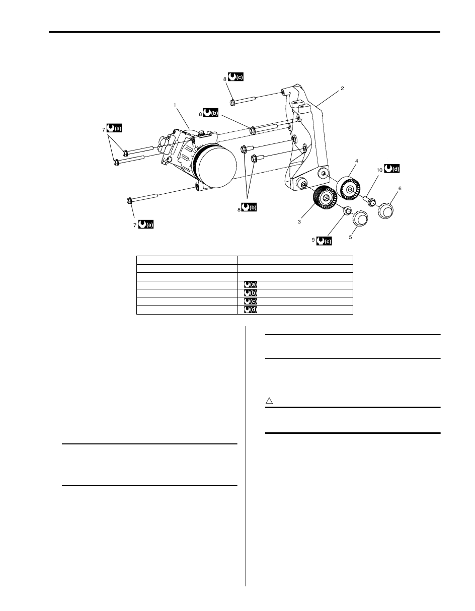
Compressor Assembly and Compressor Bracket Components

S5JB0B7206047

Compressor Assembly Removal and 
Installation

S5JB0B7206035

Removal

1) Run engine at idle with A/C ON for 10 minutes.
2) Disconnect negative (–) cable at battery.
3) Recover refrigerant from the A/C system using 

recovery and recycling equipment referring to 
“Recovery” in “Operation Procedure for Charging A/
C with Refrigerant”.

NOTE
The amount of compressor oil at removed 
must be measured and the same amount 
must be poured when installing the 
compressor.


4) Disconnect MAF sensor coupler, and then remove 

air cleaner assembly.

5) Remove A/C compressor drive belt referring to 

“Accessory Drive Belt and Idler Pulley Removal and 
Installation in Section 1J”.

6) Disconnect magnet clutch connector.
7) Disconnect suction hose and discharge hose from 

compressor.

NOTE
Cap open fitting immediately to keep 
moisture out of system.


8) Remove compressor from its mount.

Installation

CAUTION

!


Be sure to use HFC-134a (R-134a) 
compressor oil.


Reverse removal procedure noting the following 
instructions.
• If compressor is replaced, pour new compressor oil 

referring to “Precautions on Replenishing Compressor 
Oil”.

• Evacuate and charge system referring to “Evacuation” 

and “Charge” in “Operation Procedure for Charging A/
C with Refrigerant”.

• Install drive belt referring to “Accessory Drive Belt and 

Idler Pulley Removal and Installation in Section 1J”.

Tightening torque
Compressor mounting bolt :  25 N·m (2.5 kgf-m, 
18.0 lb-ft)

I5JB0B720017-05

1. Compressor assembly

8. Compressor bracket mount bolt

2. Compressor bracket

9. Idler bolt No.1

3. Idler pulley No.1

10. Idler bolt No.2

4. Idler pulley No.2

: 25 N

⋅m (2.5 kgf-m, 18.5 lb-ft)

5. Dust cover No.1

: 40 N

⋅m (4.0 kgf-m, 29.0 lb-ft)

6. Dust cover No.2

: 28 N

⋅m (2.8 kgf-m, 20.5 lb-ft)

7. Compressor mount bolt

: 50 N

⋅m (5.0 kgf-m, 36.5 lb-ft)

7B-27 Air Conditioning System: 

Magnet Clutch Components 

S5JB0B7206037

Magnet Clutch Operating Check 

S5JB0B7206039

Check the following items.
If any detects are found, repair or replace magnet clutch 
assembly.
• Inspect armature plate and rotor for signs of oil.
• Check clutch bearings for noise and grease leakage.
• Using an ohmmeter (3), measure resistance of stator 

coil between clutch lead wire (1) and body ground (2). 
If measured resistance is not within tolerance, replace 
coil.

Specified current of magnet clutch
Approx. 3.8 – 6.0 

 at 25 °C (77 °F)

2

7

3

5

6

1

4

4

(a)

I5JB0B720018-02

1. Armature plate bolt

4. Circlip

7. Compressor body assembly

2. Armature plate

5. Magnet clutch pulley

: 21 N

⋅m (2.1 kgf-m, 15.5 lb-ft)

3. Shim(s)

6. Magnet clutch coil

: Do not reuse.

3

1

2

I5JB0B720022-02

Air Conditioning System:  7B-28

Magnet Clutch Removal and Installation

S5JB0B7206041

Removal

1) Remove compressor from vehicle referring to 

“Compressor Assembly Removal and Installation”.

2) Fix armature plate (1) with special tool (A) and 

remove armature plate bolt.

Special tool
(A):  09991–06310

NOTE
Do not reuse armature plate bolt.


3) Remove armature plate.
4) Remove shim(s) from shaft.
5) Using special tool (A), remove snap ring (1).

Special tool
(A):  09900–06107

6) Remove magnet clutch pulley (1) with puller (2).

NOTE
Be careful not to damage pulley.


7) Remove snap ring (1) using special tool (B), and 

then remove magnet clutch coil (1).

Special tool
(A):  09900–06107

Installation

1) Install magnet clutch coil (3).

NOTE
Protrusion (1) on underside of magnet clutch 
coil and hole (2) on compressor body 
assembly must match to stop movement of 
magnet clutch coil and to locate lead wire 
correctly.


1

(A)

2

I5JB0A720071-01

(A)

1

I5JB0A720072-01

1

2

I5JB0A720073-01

(A)

1

I5JB0A720074-02

2

1

3

I5JB0A720075-01

7B-29 Air Conditioning System: 

2) Install new snap ring (1) using special tool (A).

Special tool
(B):  09900–06107

3) Install magnet clutch pulley.

a) Set magnet clutch horizontally over clutch 

installation boss.

b) Place special tool (B) onto magnet clutch 

bearing. Ensure that edge rests only inner rase 
of bearing.

Special tool
(B):  09951–15510

c) Install new snap ring (1) using special tool (A).

Special tool
(A):  09900–06107

4) Install armature plate (1).
5) Using special tool (A), tighten new armature plate 

bolt (2) to specified torque.

Tightening torque
Armature plate bolt (a):  21 N·m (2.1 kgf-m, 15.5 
lb-ft)

Special tool
(A):  09991–06310

6) Adjust clearance between armature plate (1) and 

magnet clutch pulley by putting shim(s) on 
compressor shaft. To measure the clearance, 
perform the following steps.
a) Put compressor in a vise.
b) Set dial gauge on magnet clutch plate, and then 

adjust its pointer at 0.

c) Connect battery positive terminal (+) to magnet 

clutch coil lead wire.

d) Connect battery negative terminal (–) to 

compressor body assembly. (At this point, 
armature plate and magnet clutch pulley (2) are 
kept in contact.)

e) Disconnect battery negative terminal (–) to 

compressor body assembly. (At this point, 
armature plate and magnet clutch pulley (2) are 
not in contact.)

f) Read stroke of armature plate from dial gauge by 

performing Step d) and e) repeatedly. (Stroke of 
armature plate is clearance between armature 
plate and magnet clutch pulley (2).)

Standard clearance between armature plate and 
magnet clutch
“a”: 0.3 – 0.6 mm (0.012 – 0.024 in.)

(A)

1

1

I5JB0A720088-04

(B)

I5JB0A720076-02

(A)

1

1

I5JB0A720077-01

2

1, (a)

(A)

I5JB0B720019-01

1

2

2

1

“a”

I5JB0A720078-02


Content   ..  128  129  130  131   ..