Suzuki Grand Vitara JB419. Manual - part 95
 

  Index      Suzuki     Suzuki Grand Vitara JB419 (with F9Q engine) - service repair manual 2007 year


Search            


Content   ..  93  94  95  96   ..


Suzuki Grand Vitara JB419. Manual - part 95


Electronic Stability Program:  4F-13

DTC Check

S5JB0B4604050

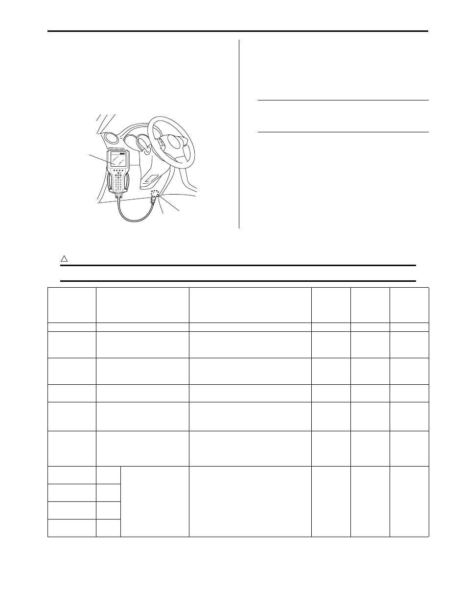
1) Turn ignition switch to OFF position.
2) Connect SUZUKI scan tool to data link connector 

(1).

Special tool
(A):  SUZUKI scan tool

3) Turn ignition switch to ON position.
4) Read DTC according to instructions displayed on 

SUZUKI scan tool and print it or write it down. Refer 
to SUZUKI scan tool operator’s manual for further 
details.

NOTE
If SUZUKI scan tool can not communicate 
ESP

® control module, perform “Serial Data 

Link Circuit Check”.


5) After completing the check, turn ignition switch off 

and disconnect SUZUKI scan tool from DLC.

DTC Table

S5JB0B4604051

CAUTION

!


Be sure to perform “Electronic Stability Program Check” before starting diagnosis.


(A)

1

I5JB0A450008-01

DTC 

(displayed 

on SUZUKI 

scan tool)

Diagnostic Items

Detecting condition (DTC will be 

set when detecting)

ABS 

warning 

lamp

EBD 

warning 

lamp

ESP

® 

warning 

lamp

NO DTC

Normal

)

C1015

Longitudinal G sensor in 
yaw rate / G sensor 
assembly failure

Longitudinal G sensor signal is out of 
specified range. (for 4WD vehicle)

{

{

)

C1016

Stop lamp switch failure

Vehicle behavior and stop lamp 
switch signal is disagreed for 
specified time.

)

C1017

Lateral G sensor in yaw rate 
/ G sensor assembly failure

Lateral G sensor signal is out of 
specified range.

{

)

C1018

Brake fluid level switch 
failure

• Brake fluid level is too low.
• Input voltage of brake fluid level 

switch to BCM is low.

{

)

C1020

Master cylinder pressure 
sensor power supply failure

Power supply voltage to master 
cylinder pressure sensor in ESP

® 

hydraulic unit / control module 
assembly is too low.

{

)

C1021

RF

Wheel speed 
sensor circuit failure

Wheel sensor signal is out of 
specified range.

{

*1

{

)

C1025

LF

)

C1031

RR

)

C1035

LR

4F-14 Electronic Stability Program: 

)

C1022

RF

Wheel speed 
sensor or encoder 
failure

Abnormal wheel speed sensor signal 
is detected.

{

*1

{

)

C1026

LF

)

C1032

RR

)

C1036

LR

)

C1023

Yaw rate sensor in yaw rate 
/ G sensor assembly failure

• Yaw rate sensor signal is out of 

range.

• Vehicle behavior and yaw rate 

signal is disagreed.

{

)

C1024

Steering angle sensor 
circuit failure

• Steering angle sensor internal 

defect is detected by CPU in 
steering angle sensor.

• Steering angle sensor signal is out 

of specified range.

{

)

C1027

ESP

® OFF switch circuit 

failure

Mechanical switch failure, failure in 
switch wiring is shorted to ground.

)

C1028

Master cylinder pressure 
sensor circuit failure

Input signal voltage from master 
cylinder pressure sensor in ESP

® 

control module is too high or low.

{

)

C1034

Yaw rate / G sensor 
assembly power supply 
failure

Power supply voltage of yaw rate / G 
sensor assembly is too high when 
ignition switch OFF.

*2

{

Power supply voltage of yaw rate / G 
sensor assembly is too low when 
ignition switch ON.

)

C1037

Steering angle sensor 
power supply failure

Power supply voltage to steering 
angle sensor is too low.

{

)

C1038

Steering angle sensor 
detect rolling counter failure 
with ESP

® control module

ESP

® control module rolling counter 

failure is detected by steering angle 
sensor.

{

)

C1039

Yaw rate / G sensor 
assembly internal failure

Yaw rate / G sensor assembly 
internal failure is detected.

*2

{

)

C1040

Stability control system 
function failure

Stability control is active for more 
than specified time without yaw rate 
change.

{

DTC 

(displayed 

on SUZUKI 

scan tool)

Diagnostic Items

Detecting condition (DTC will be 

set when detecting)

ABS 

warning 

lamp

EBD 

warning 

lamp

ESP

® 

warning 

lamp

Electronic Stability Program:  4F-15

)

C1041

RF

Inlet solenoid valve 
circuit failure

Mismatching solenoid output and 
solenoid monitor is detected.

{

{

{

)

C1042

Outlet solenoid 
valve circuit failure

)

C1045

LF

Inlet solenoid valve 
circuit failure

)

C1046

Outlet solenoid 
valve circuit failure

)

C1051

RR

Inlet solenoid valve 
circuit failure

)

C1052

Outlet solenoid 
valve circuit failure

)

C1055

LR

Inlet solenoid valve 
circuit failure

)

C1056

Outlet solenoid 
valve circuit failure

)

C1043

Master cylinder cut solenoid 
valve circuit No.1 failure

)

C1044

Master cylinder cut solenoid 
valve circuit No.2 failure

)

C1053

Low pressure solenoid 
valve circuit No.1 failure

)

C1054

Low pressure solenoid 
valve circuit No.2 failure

)

C1050

Back switch failure (for M/T 
model)

Back up light switch and/or switch 
circuit failure is detected.

{

)

C1057

ESP

® (ABS) control 

module power supply circuit 
failure *3

ESP

® (ABS) control module power 

supply voltage is too high.

{

{

{

ESP

® (ABS) control module power 

supply voltage is too low.

{

*5

{

)

C1061

Pump motor and/or motor 
circuit failure

Defective pump motor and/or motor 
power supply voltage is too low.

{

{

)

C1063

Solenoid valve power 
supply driver circuit failure

Mismatching solenoid output and 
solenoid monitor is detected.

{

{

{

)

C1071

ESP

® (ABS) control 

module internal defect

ESP

® (ABS) control module internal 

defect is detected.

{

{

{

)

C1073

Lost communication with 
yaw rate / G sensor 
assembly

CAN line communication error in 
ESP

® control module and yaw rate / 

G sensor assembly is detected.

*2

{

)

C1075

Steering angle sensor 
calibration incomplete *4

Missing steering angle sensor 
calibration point data is detected.

)

C1076

Master cylinder pressure 
sensor calibration 
incomplete

Master cylinder pressure sensor 
calibration is incompleted.

{

)

C1077

Longitudinal G sensor in 
yaw rate / G sensor 
assembly calibration 
incomplete

Longitudinal G sensor in yaw rate / G 
sensor assembly calibration is 
incompleted. (for 4WD vehicle)

{

{

)

C1078

Lateral G sensor in yaw rate 
/ G sensor assembly 
calibration incomplete

Lateral G sensor in yaw rate / G 
sensor assembly calibration is 
incompleted.

{

)

C1090

ECM detect rolling counter 
failure with ESP

® control 

module

ESP

® control module rolling counter 

failure is detected by ECM.

{

DTC 

(displayed 

on SUZUKI 

scan tool)

Diagnostic Items

Detecting condition (DTC will be 

set when detecting)

ABS 

warning 

lamp

EBD 

warning 

lamp

ESP

® 

warning 

lamp

4F-16 Electronic Stability Program: 

NOTE

• “{” in ABS warning lamp, EBD warning lamp and ESP

® warning lamp column of the above table 

means warning lamp is lit when DTC is detected.

• *1: If two or more wheel speed sensor are defective, ABS warning lamp, EBD warning lamp and 

ESP

® warning lamp are lit and all the control functions are deactivated. If one wheel speed sensor is 

defective, ABS warning lamp and ESP

® warning lamp are lit and ABS and TCS / stability control are 

deactivated.

• *2: For 4WD vehicle, ABS warning lamp and ESP

® warning lamp are lit and ABS and TCS / stability 

control are deactivated. For 2WD vehicle, ESP

® warning lamp is lit and TCS / stability control is 

deactivated.

• *3: SLIP indicator lamp and ESP

® OFF lamp turn ON when power supply circuit voltage is low.

• *4: SLIP indicator lamp flashes continuously at Intervals of 1 Hz.
• *5: EBD warning lamp is lit when power supply circuit voltage is too low.


)

C1091

ECM data in CAN line 
failure

ECM sent invalid signal to ESP

® 

control module.

{

)

C1093

4WD control module data in 
CAN line failure (if equipped 
4WD control module)

4WD control module sent invalid 
signal to ESP

® control module

)

U1073

Control module 
communication bus off

Transmission error that is 
inconsistent between transmission 
data and transmission monitor (CAN 
bus monitor) data is detected more 
than 7 times continuously.

{

)

U1100

Lost communication with 
ECM (reception error)

ECM message data is missing from 
CAN communication.

{

)

U1126

Lost communication with 
steering angle sensor 
(reception error)

Steering angle sensor message data 
is missing from CAN communication.

)

U1139

Lost communication with 
4WD control module 
(reception error) (if 
equipped 4WD control 
module)

4WD control module message data 
is missing from CAN communication. 

)

U1140

Lost communication with 
BCM (reception error)

BCM message data is missing from 
CAN communication.

DTC 

(displayed 

on SUZUKI 

scan tool)

Diagnostic Items

Detecting condition (DTC will be 

set when detecting)

ABS 

warning 

lamp

EBD 

warning 

lamp

ESP

® 

warning 

lamp


Content   ..  93  94  95  96   ..