Suzuki Grand Vitara JB419. Manual - part 81
Transfer: 3C-22
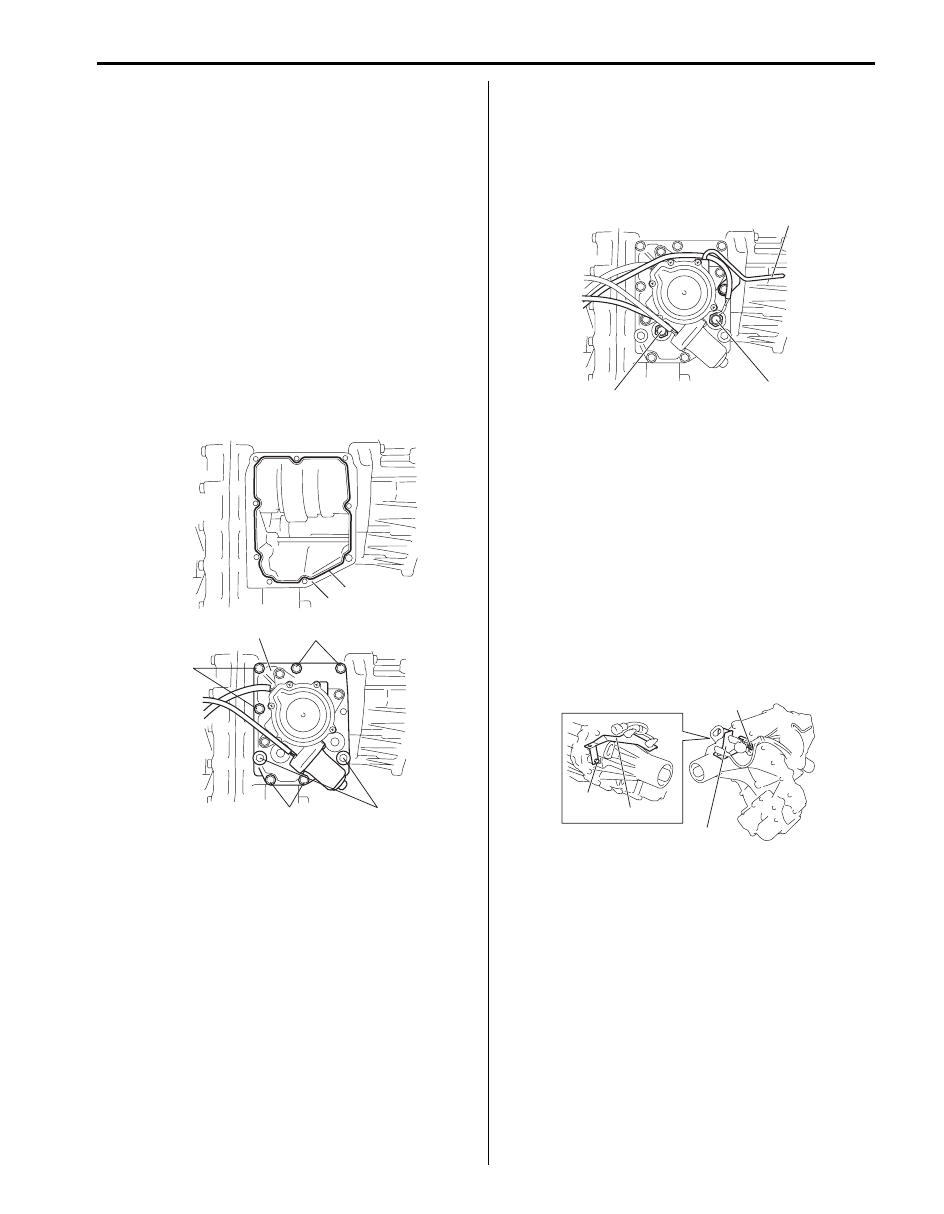
22) Clean mating surface of control cover (1) and center
case (2), apply sealant to center case as shown in
figure by such amount that its section is 1.2 mm
(0.047 in.) in diameter, confirm the each fork of
control cover is in groove of the sleeve, mate control
cover with center case and then tighten control cover
bolts (3) to which thread lock cement has been
applied and control cover dowel bolts (4) to specified
torque.
“A”: Sealant 99000–31260 (SUZUKI Bond
No.1217G)
“B”: Thread lock cement 99000–32110 (Thread
Lock Cement Super 1322)
Tightening torque
Control cover bolt (a): 23 N·m (2.3 kgf-m, 17.0 lb-
ft)
Control cover dowel bolt (b): 23 N·m (2.3 kgf-m,
17.0 lb-ft)
23) Install center differential lock switch (1), 4L/N switch
(2) and breather pipe (3).
Tightening torque
Center differential lock switch (a): 20 N·m (2.0
kgf-m, 14.5 lb-ft)
4L/N switch (b): 20 N·m (2.0 kgf-m, 14.5 lb-ft)
24) Install front output flange as follows, if equipped.
a) Install front output flange nut while holding flange
by using special tool.
b) Caulk flange nut.
Special tool
: 09922–66021
Tightening torque
Flange nut: 125 N·m (12.5 kgf-m, 90.5 lb-ft)
25) Install harness bracket (1).
Tightening torque
Harness bracket bolt (a): 10 N·m (1.0 kgf-m, 7.5
lb-ft)
“A”
2
1
3, “B”, (a)
3, “B”, (a)
3, “B”, (a)
4, “B”, (b)
I5JB0A331051-04
3
2, (b)
1, (a)
I5JB0A331052-02
(a)
(a)
1
1
I5JB0A331053-01