Suzuki Grand Vitara JB627. Manual - part 254
 

  Index      Suzuki     Suzuki Grand Vitara JB627 - service repair manual


Search            


Content   ..  252  253  254  255   ..


Suzuki Grand Vitara JB627. Manual - part 254


5C-7 Clutch: 

Installation
Reverse removal procedure for installation noting the 
following.
• Apply grease to push rod clevis pin (1).

“A”:  Grease 99000–25100 (SUZUKI Silicone Grease)

• Tighten master cylinder attaching nuts (2) to specified 

torque.

Tightening torque
Clutch master cylinder attaching nut (a):  23 N·m (
2.3 kgf-m, 17.0 lb-ft)

• Fill reservoir with specified brake fluid and check fluid 

leakage.

• After installation, bleed air from clutch system and 

check clutch pedal free travel. Refer to “Air Bleeding 
of Brake System in Section 4A” 
for air bleeding 
procedure.

Clutch Master Cylinder Inspection

S6JB0B5306006

• Check master cylinder (1) for damage and fluid 

leakage, boot for damage and deterioration, gasket 
for damage and deterioration.

• Check for push rod clevis distance “a” and clevis pin 

hole diameter “b” as shown.

If any malfunction is found, replace master cylinder.

Push rod clevis distance “a”:
106.1 – 107.1 mm (4.18 – 4.22 in.)

Clevis pin hole diameter “b”:
10.05 – 10.15 mm (0.396 – 0.399 in.)

Clutch Operating Cylinder Assembly Removal 
and Installation

S6JB0B5306007

CAUTION

!


• Do not allow fluid to get on painted 

surfaces. It may cause painted surface 
damage.

• Do not disassemble clutch operating 

cylinder assembly.


Removal

1) Clean around reservoir cap of brake master cylinder 

and take out fluid with syringe or such.

2) Dismount transmission assembly referring to 

“Manual Transmission Assembly Dismounting and 
Remounting in Section 5B”.

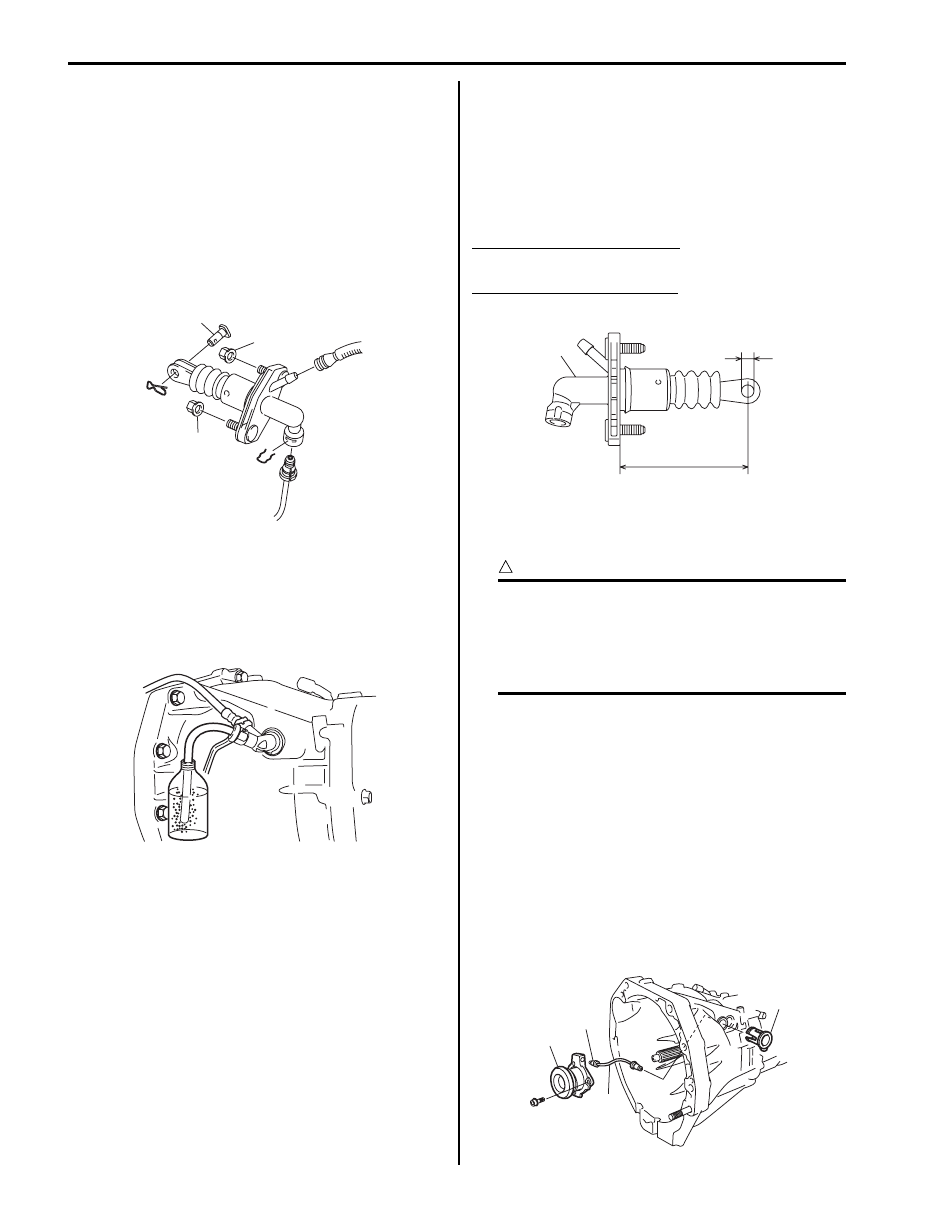
3) Loosen clutch fluid pipe flare nut (1) of clutch 

operating cylinder assembly (2).

4) Remove clutch pipe joint sleeve (3) from 

transmission front case and then remove clutch fluid 
pipe (4).

5) Remove clutch operating cylinder assembly from 

transmission front case.

1, “A”

2, (a)

2, (a)

I5JB0A530014-01

I5JB0A530015-03

“b”

“a”

1

I5JB0A530016-01

3

1

2

4

I5JB0A530017-01

Clutch: 5C-8

Installation

1) Install clutch operating cylinder assembly (2) to 

transmission front case. Tighten mounting bolts to 
specified torque.

Tightening torque
Clutch operating cylinder assembly mounting 
bolt (a):  10 N·m (1.0 kgf-m, 7.5 lb-ft)

2) Connect clutch fluid pipe (4) to clutch operating 

cylinder assembly temporarily.

3) Install clutch pipe joint sleeve (3) to transmission 

front case securely and then tighten clutch fluid pipe 
flare nut (1) to specified torque.

Tightening torque
Clutch fluid pipe flare nut (b):  16 N·m (1.6 kgf-
m, 11.5 lb-ft)

4) Remount transmission assembly referring to 

“Manual Transmission Assembly Dismounting and 
Remounting in Section 5B”
.

5) Fill reservoir with specified brake fluid and check for 

fluid leakage.

6) Bleed air from system and check clutch pedal free 

travel. Refer to “Air Bleeding of Brake System in 
Section 4A”
 for air bleeding procedure.

Clutch Operating Cylinder Assembly Inspection
Check clutch fluid leakage, spring for damage and 
bearing for smooth rotation. If malfunction is found, 
replace clutch operating cylinder assembly.

Clutch Cover, Clutch Disc and Flywheel Components

S6JB0B5306008

3

1, (b)

2

4

(a)

I5JB0A530018-01

I5JB0A530015-03

I5JB0A530022-01

1. Input shaft bearing

4. Clutch cover

: 23 N

⋅m (2.3 kgf-m, 17.0 lb-ft)

2. Flywheel

5. Clutch cover bolt

: 68.5 N

⋅m (6.9 kgf-m, 49.5 lb-ft)

3. Clutch disc

6. Flywheel bolt

: Do not reuse.

5C-9 Clutch: 

Clutch Cover, Clutch Disc and Flywheel 
Removal and Installation

S6JB0B5306009

Removal

1) Dismount transmission assembly referring to 

“Manual Transmission Assembly Dismounting and 
Remounting in Section 5B”.

2) Hold flywheel stationary with special tool and remove 

clutch cover bolts (1), clutch cover (2) and clutch 
disc.

Special tool
(A):  09924–17811 

3) Pull out input shaft bearing (1) by using special tools.

Special tool
(A):  09921–26020
(B):  09930–30104

4) Remove flywheel from crankshaft.

Installation

NOTE
Before installation, make sure that flywheel 
surface and pressure plate surface have 
been cleaned and dried thoroughly.


1) Install flywheel (1) to crankshaft and tighten new 

bolts (2) to specification.

Special tool
(A):  09924–17811

Tightening torque
Flywheel bolt (a):  68.5 N·m (6.9 kgf-m, 49.5 lb-ft)

2) Using special tool, install input shaft bearing to 

flywheel.

Special tool
(B):  09925–98210

IYSQ01530019-01

I2RH01530023-01

I5JB0A530020-01

IYSQ01530022-01

Clutch: 5C-10

3) Aligning clutch disc to flywheel center by using 

special tool, install clutch cover (1) and bolts (2). 
Then tighten bolts to specification.

NOTE

• While tightening clutch cover bolts, 

compress clutch disc with special tool by 
hand so that disc centered.

• Tighten cover bolts little by little evenly in 

diagonal order.


Special tool
(A):  09924–17811
(C):  09923–36320

Tightening torque
Clutch cover bolt (b):  23 N·m (2.3 kgf-m, 17.0 lb-
ft)

4) Slightly apply grease to input shaft (1). 

“A”:  Grease 99000–25210 (SUZUKI Super 
Grease I)

5) Join transmission assembly with engine.

Refer to “Manual Transmission Assembly 
Dismounting and Remounting in Section 5B”.

NOTE
Turn crankshaft with wrench from front while 
inserting transmission input shaft (1) to 
clutch disc until splines mesh.


Clutch Cover, Clutch Disc and Flywheel 
Inspection

S6JB0B5306010

Input Shaft Bearing
Check bearing for smooth rotation and replace it if 
abnormality is found.

Clutch Disc
Measure depth of rivet head depression, i.e. distance 
between rivet head and facing surface. If depression is 
found to have reached service limit at any of holes, 
replace disc assembly.

Rivet head depth
Standard: 1.5 mm (0.06 in.)
Service limit: 0.5 mm (0.02 in.)

Clutch Cover
• Check diaphragm spring for abnormal wear or 

damage.

• Inspect pressure plate for wear or heat spots.
If abnormality is found, replace it as assembly. Do not 
disassemble it into diaphragm and pressure plate.

Flywheel
Check surface contacting clutch disc for abnormal wear 
or heat spots. Replace or repair as required.

IYSQ01530023-01

1, “A”

I5JB0A530021-01

IYSQ01530025-01


Content   ..  252  253  254  255   ..