Suzuki Grand Vitara JB627. Manual - part 153
 

  Index      Suzuki     Suzuki Grand Vitara JB627 - service repair manual


Search            


Content   ..  151  152  153  154   ..


Suzuki Grand Vitara JB627. Manual - part 153


3C-16 Transfer: 

Detail of 4WD Control System Check
Step 1: Customer complaint analysis
Record details of the problem (failure, complaint) and how it occurred as described by the customer.
For this purpose, use of such a questionnaire form as shown in the following will facilitate collecting information to the 
point required for proper analysis and diagnosis.

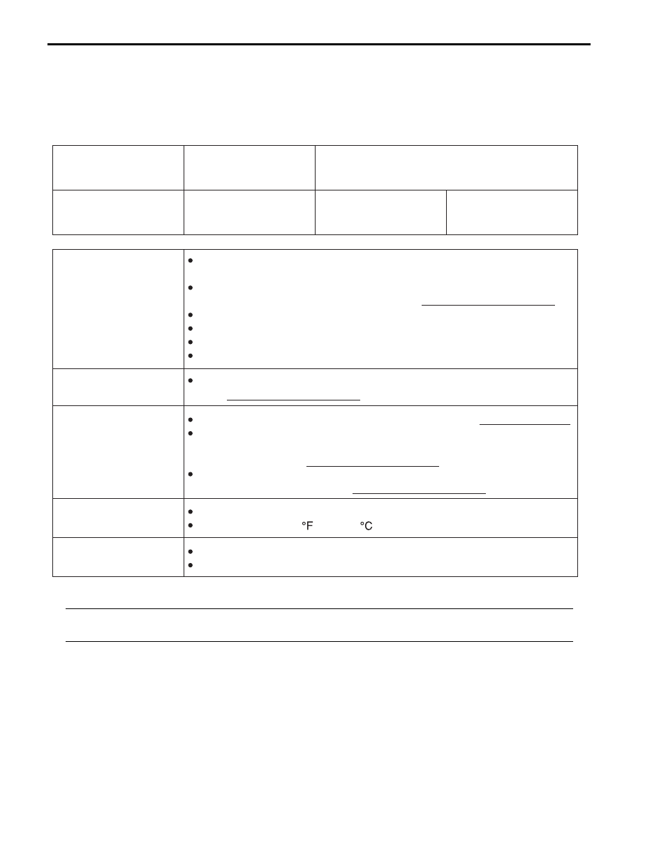
Customer questionnaire (Example)

NOTE
The form is a standard sample. It should be modified according to conditions characteristic of each 
market.


Customer’s name:

Model:

VIN:

Problem Symptoms

Frequency of Occurrence

Conditions for 
Occurrence of Ploblem

Environmental Condition

Diagnostic Trouble Code

Date of Reg:

Transfer position indicator abnormal: fails to turn on / fails to turn off / 
flashes
Abnormal noise while vehicle running: from transfer, from actuator, 
                                                             other
No shifted to “4H” position
No shifted to “4H-lock” position
No shifted to “4L-lock” position
No shifted to “N” position

When starting: at initial start only / at every start / other
Vehicle speed: while accelerating / while decelerating / at stop / 
                         while turning / while running at constant speed / 
                         other
Road surface condition: Paved road / rough road / snow-covered road / 
                                       other

Wheather: fine / cloudy / rain / snow / other
Temperature:                (                 )

First check:                              Normal code / malfunction code (               )
Second check after test drive: Normal code / malfunction code (               )    

Continuous / Intermittent   (           times a day, a month) / 
other

Date of problem:

Mileage:

Date of issue:

I5JB0A332011-02

Transfer: 3C-17

Step 2. DTC / freeze frame data check, record and 
clearance
First, referring to “DTC Check”, check DTC and pending 
DTC. If DTC exists, print or write down DTC and freeze 
frame data and then clear malfunction DTC(s) by 
referring to “DTC Clearance”. Malfunction DTC indicates 
malfunction in the system but it is not possible to know 
from it whether the malfunction is occurring now or it 
occurred in the past and normal condition has been 
restored. In order to know that, check symptom in 
question according to Step 5 and then recheck DTC 
according to Step 6.
Diagnosing a trouble based on the DTC in this step only 
or failure to clear the DTC in this step may result in an 
faulty diagnosis, trouble diagnosis of a normal circuit or 
difficulty in troubleshooting which is otherwise 
unnecessary.

Step 3 and 4. Visual inspection
As a preliminary step, be sure to perform visual check of 
the items that support proper function of the 4WD control 
system referring to “Visual Inspection”.

Step 5. Trouble symptom confirmation
Check trouble symptoms based on information obtained 
in “Step 1: Customer complaint analysis: ” and “Step 2. 
DTC / freeze frame data check, record and clearance: ”.
Also, reconfirm DTC according to “DTC Confirmation 
Procedure” described in each DTC flow.

Step 6 and 7. Rechecking and record of DTC and 
freeze frame data
Refer to “DTC Check” for checking procedure.

Step 8. 4WD control symptom diagnosis
Check the parts of the system suspected as a possible 
cause referring to “4WD Control Symptom Diagnosis”.

Step 9. Troubleshooting for DTC
Based on the DTC indicated in Step 6 / 7 and referring to 
“applicable DTC flow”, locate the cause of the trouble, 
namely in a sensor, switch, wire harness, connector, 
actuator, 4WD control module or other part and repair or 
replace faulty parts.

Step 10. Check for intermittent problem
Check parts where an intermittent trouble is easy to 
occur (e.g. wire harness, connector, etc.), referring to 
“Intermittent and Poor Connection Inspection in Section 
00”
 and related circuit of DTC recorded in Step 2.

Step 11. Final confirmation test
Confirm that the problem symptom has gone and the 
vehicle is free from any abnormal conditions. If what has 
been repaired is related to the malfunction DTC, clear 
the DTC once and check to ensure that no malfunction 
DTC is indicated.

Transfer Position Indicator Operation Check

S6JB0B3304002

1) Turn ignition switch to OFF position.
2) Check that transfer position indicators turn on for 

about 2 seconds and then turns off.
If any faulty condition is found, proceed to “Transfer 
Position Indicator Does Not Come ON at Ignition 
Switch ON but Engine Stops” or
 “Transfer Position 
Indicator Remains ON Steady at Ignition Switch ON”.

4WD Control System Operation Inspection

S6JB0B3304003

NOTE

• If it is difficult to shift between “4H” and 

“4H-lock” while vehicle is moving, stop 
vehicle and operate Transfer switch.

• When ABS operates while shifting from 

“4H” to “4H-lock” (“4H-lock” to “4H”), it 
becomes to disagreement of transfer 
switch and transfer position. End of the 
ABS operation, and then transfer shifting 
from “4H” to “4H-lock” (“4H-lock” to “4H”).

• Transfer position indicator blinks during 

shifting process.

• Transfer position indicator blinks and 

warning buzzer sounds during “N” 
position at intervals of 3 seconds.

• When shifting to “N” or “4L-lock” does not 

shifts, try the following procedure.
– For M/T model, shift transmission to N 

(Neutral) position, turn ignition switch to 
ON position, depress clutch pedal and 
brake pedal while engine is running, and 
then try shifting again.

– For A/T model, turn ignition switch to 

ON position, move vehicles lowly back 
or forth a few feet, depress brake pedal, 
and then try shifting again.


1) Inspect shift operation from 4H to 4H-lock as follows.

a) Start engine.
b) Position front wheels straight ahead.
c) Confirm that vehicle is under following 

conditions.
• Transfer shift position is 4H.
• Vehicle speed is less than 100 km/h (60 mph).

d) Turn transfer switch to “4H-lock” position.
e) Check that differential lock indicator blinks, and 

then comes ON steady.

3C-18 Transfer: 

2) Inspect shift operation from 4H-lock to 4L-lock as 

follows.
a) Stop vehicle completely with engine running.
b) Position front wheels straight ahead.
c) Confirm that vehicle is under following 

conditions.
• Transfer shift position is 4H-lock.
• Transmission shift lever is at “N” position. (for 

A/T model)

• Clutch pedal is depressed fully. (for M/T 

model)

• Brake pedal is depressed.

d) Push and turn transfer switch to “4L-lock” 

position.

e) Check that 4L indicator blink, and then 

differential lock indicator and 4L indicator comes 
ON steady.

3) Inspect shift operation from 4L-lock to 4H-lock as 

follows.
a) Stop vehicle completely with engine running.
b) Position front wheels straight ahead.
c) Confirm that vehicle is under following 

conditions.
• Transfer shift position is 4L-lock.
• Transmission shift lever is at “N” position. (for 

A/T model)

• Clutch pedal is depressed fully. (for M/T 

model)

• Brake pedal is depressed.

d) Push and turn transfer switch to “4H-lock” 

position.

e) Check that 4L indicator blink, and then 

differential lock indicator comes ON steady and 
4L indicator not come ON.

4) Inspect shift operation from 4H-lock to 4H as follows.

a) Start engine.
b) Position front wheels straight ahead.
c) Confirm that vehicle is under following 

conditions.
• Transfer shift position is 4H-lock.
• Vehicle speed is less than 100 km/h (60 mph).

d) Turn transfer switch to “4H” position.
e) Check that differential lock indicator blinks, and 

then not comes ON.

5) Inspect shift operation from 4H to N as follows.

a) Stop vehicle completely with engine running.
b) Position front wheels straight ahead.
c) Confirm that vehicle is under following 

conditions.
• Transfer shift position is 4H.
• Transmission shift lever is at “N” position. (for 

A/T model)

• Clutch pedal is depressed fully. (for M/T 

model)

• Brake pedal is depressed.

d) Turn transfer switch to “†” position (1), keep it 

there for about 10 seconds, and then turn it to 
“N” position after N indicator blinks.

e) Check that N indicator blinks and warning buzzer 

sounds, and then N indicator comes ON steady.

Visual Inspection

S6JB0B3304004

Check the following parts and systems visually.

1

I5JB0A332002-01

Inspection Item

Referring

• Front differential oil ---- level, leakage

“Front Differential Oil Change: Front in Section 3B”

• Rear differential oil ---- level, leakage

“Rear Differential Oil Change: Rear in Section 3B”

• Transfer gear oil ---- level, leakage

“Transfer Oil Change”

• Manual transmission oil ---- level, leakage

“Manual Transmission Oil Change in Section 5B”

• A/T fluid ---- level, leakage

“A/T Fluid Level Check in Section 5A”

• Transfer mounting(s) ---- wear and looseness
• Fuses ---- burning
• Battery ---- fluid level, corrosion of terminal

“Battery Inspection in Section 1J”

• Connectors of electric wire harness ---- disconnection, 

friction

“Intermittent and Poor Connection Inspection in Section 
00”

• Other parts that can be checked visually

Transfer: 3C-19

DTC Check

S6JB0B3304005

Using SUZUKI Scan Tool

1) Turn ignition switch to OFF position.
2) Connect SUZUKI scan tool to data link connector 

(DLC) (1) located on underside of instrument panel.

Special tool
(A):  SUZUKI scan tool

3) Turn ignition switch to ON position.
4) Read DTC according to instructions displayed on 

SUZUKI scan tool and print it or write it down. Refer 
to SUZUKI scan tool operator’s manual for further 
details.
If communication between SUZUKI scan tool and 
4WD control module is not possible, check if 
SUZUKI scan tool is communicable by connecting it 
to 4WD control module in another vehicle. If 
communication is possible in this case, SUZUKI 
scan tool is in good condition. Then check data link 
connector and serial data line (circuit) in the vehicle 
with which communication was not possible.

5) After completing the check, turn ignition switch OFF 

and disconnect SUZUKI scan tool from data link 
connector (DLC).

Using Diagnosis Connector

1) With ignition switch OFF position, using service wire 

short diagnosis switch terminal (1) of diagnosis 
connector (2) and body ground.

2) With ignition switch ON position and leaving engine 

OFF, read DTC displayed on digital display odometer 
(3) of combination meter referring to “DTC Table”.

NOTE
When more than 2 DTCs are stored in 
memory, flashing for each DTC is repeated 
three times starting with the smallest DTC 
number in increasing order.


3) After completing the check, turn ignition switch OFF, 

disconnect service wire from diagnosis connector.

(A)

1

I5JB0A332012-01

1

2

3

I5JB0A332013-01


Content   ..  151  152  153  154   ..