Suzuki Grand Vitara JB627. Manual - part 77
 

  Index      Suzuki     Suzuki Grand Vitara JB627 - service repair manual


Search            


Content   ..  75  76  77  78   ..


Suzuki Grand Vitara JB627. Manual - part 77


1C-6 Engine Electrical Devices: 

Accelerator Pedal Position (APP) Sensor 
Assembly On-Vehicle Inspection

S6JB0B1306006

1) Check that accelerator pedal position (APP) sensor 

assembly has been mounted to vehicle body 
properly (no pinched floor carpet, etc.).
If mounting is not properly, reinstall accelerator pedal 
position (APP) sensor assembly properly referring to 
“Accelerator Pedal Position (APP) Sensor Assembly 
Removal and Installation”.

2) Connect scan tool to DLC with ignition switch turned 

OFF.

3) Turn ON ignition switch and select “Data List” mode 

on scan tool.

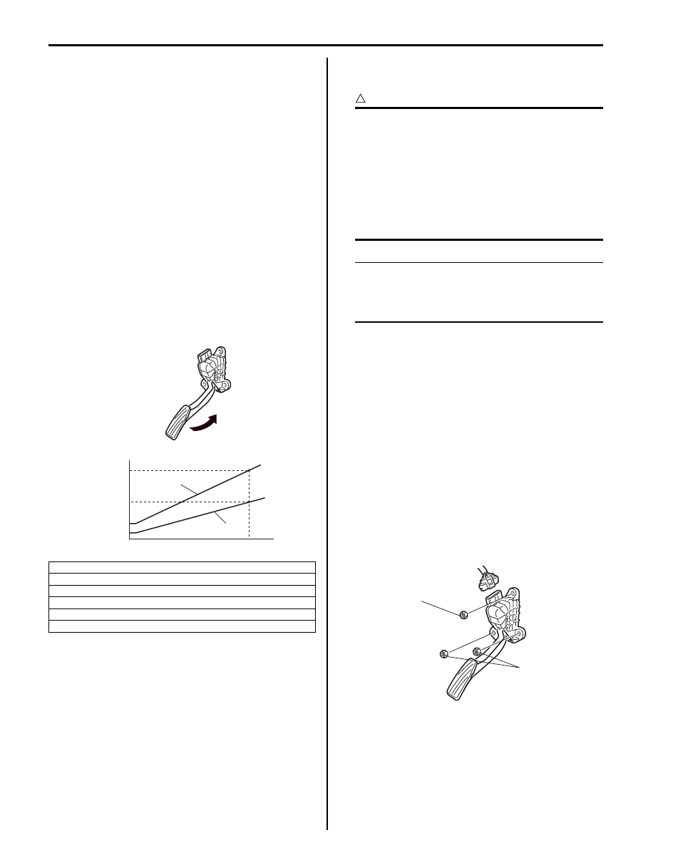
4) Check that accelerator pedal position sensor voltage 

varies as the following graph.
If sensor voltage is out of specified value or does not 
vary linearly as the following graph, check 
accelerator pedal position (APP) sensor assembly 
referring to “Accelerator Pedal Position (APP) 
Sensor Assembly Inspection”.

Accelerator Pedal Position (APP) Sensor 
Assembly Removal and Installation

S6JB0B1306007

CAUTION

!


• Do not expose accelerator pedal position 

(APP) sensor assembly to excessive shock 
like a dropping it. If accelerator pedal 
position (APP) sensor assembly has been 
exposed to excessive shock, it should be 
replaced.

• Be careful not to expose sensor section of 

accelerator pedal position (APP) sensor 
assembly to water.


NOTE
After replacing accelerator pedal position 
(APP) sensor assembly, perform calibration 
of throttle valve referring to “Electric Throttle 
Body System Calibration”.


Removal

1) Disconnect negative cable at battery.
2) Disconnect connector from accelerator pedal 

position (APP) sensor assembly.

3) Remove accelerator pedal position (APP) sensor 

assembly from its bracket.

Installation
Reverse removal procedure for installation noting the 
following.
• Tighten accelerator pedal position (APP) sensor 

assembly upper nut (1) first and then lower nuts (2) to 
specified torque.

Tightening torque
Accelerator pedal position (APP) sensor assembly 
nut (a):  6.0 N·m (0.6 kgf-m, 4.5 lb-ft)

• If APP sensor assembly bracket is removed, tighten 

its mounting nuts to specified torque.

Tightening torque
APP sensor assembly bracket nut (a):  6.0 N·m (
0.6 kgf-m, 4.3 lb-ft)

• Connect connector to accelerator pedal position 

(APP) sensor assembly securely.

[A]: Accelerator pedal position (APP) sensor (main) voltage
[B]: Accelerator pedal position (APP) sensor (sub) voltage

[C]: Sensor output voltage
[D]: Idle position of accelerator pedal

[E]: Full depressed position of accelerator pedal

[F]: Pedal stroke

[C]

[B]

[D]

[F]

[E]

[A]

1.74 - 2.17 V

0.65 - 0.82 V

3.50 - 4.27 V

0.30 - 0.44 V

I5JB0A130018-05

1, (a)

2, (a)

I5JB0A130036-01

Engine Electrical Devices:  1C-7

Accelerator Pedal Position (APP) Sensor 
Assembly Inspection

S6JB0B1306008

Check accelerator pedal position (APP) sensor (main 
and sub) output voltage as following steps.

1) For accelerator pedal position (APP) sensor (main), 

arrange 3 new 1.5 V batteries (1) in series (check 
that total voltage is 4.7 – 5.0 V) and connect its 
positive terminal to “Vin 1” terminal (2) and negative 
terminal to “Ground 1” terminal (3) of sensor. Then 
using voltmeter, connect positive terminal to “Vout 1” 
terminal (4) of sensor and negative terminal to 
battery.

2) For accelerator pedal position (APP) sensor (sub), 

arrange 3 new 1.5 V batteries (1) in series (check 
that total voltage is 4.7 – 5.0 V) and connect its 
positive terminal to “Vin 2” terminal (2) and negative 
terminal to “Ground 2” terminal (3) of sensor. Then 
using voltmeter, connect positive terminal to “Vout 2” 
terminal (4) of sensor and negative terminal to 
battery.

3) Measure output voltage variation while accelerator 

pedal is no depressed and fully depressed as 
following specification.

If sensor voltage is out of specified value or does not 
vary linearly as the following graph, replace accelerator 
pedal position (APP) sensor assembly.

Accelerator pedal position (APP) sensor output 
voltage variation
Accelerator pedal position (APP) sensor (main) 
output voltage variation [A]: 0.82 – 3.50 V at 
minimum variation, varying according to depressed 
extent of accelerator pedal
Accelerator pedal position (APP) sensor (sub) 
output voltage variation [B]: 0.44 – 1.74 V at 
minimum variation, varying according to depressed 
extent of accelerator pedal

Engine Coolant Temperature (ECT) Sensor 
Removal and Installation

S6JB0B1306009

Removal

1) Disconnect negative cable from battery.
2) Drain cooling system.
3) Disconnect coupler from ECT sensor (1).
4) Remove ECT sensor (1) from water outlet cap (2).

1

2

3

4

I5JB0A130019-02

1

2

3

4

I5JB0A130020-02

[C]: Sensor output voltage
[D]: Idle position of accelerator pedal

[E]: Fully depressed position of accelerator pedal

[F]: Pedal stroke

[C]

[B]

[D]

[F]

[E]

[A]

1.74 - 2.17 V

0.65 - 0.82 V

3.50 - 4.27 V

0.30 - 0.44 V

I5JB0A130021-05

1

2

I6JB01130014-01

1C-8 Engine Electrical Devices: 

Installation
Reverse removal procedure noting the following.
• Clean mating surfaces of sensor and water outlet cap 

(1).

• Use new O-ring.
• Tighten ECT sensor to specified torque.

Tightening torque
ECT sensor (a):  12 N·m (1.2 kgf-m, 8.5 lb-ft)

• Connect coupler to sensor securely.
• Refill cooling system.

Engine Coolant Temperature (ECT) Sensor 
Inspection

S6JB0B1306010

Immerse temperature sensing part of ECT sensor in 
water and measure resistance between sensor terminals 
while heating water gradually. If measured resistance 
doesn’t show characteristics as shown in the figure, 
replace ECT sensor.

Manifold Absolute Pressure (MAP) Sensor 
Removal and Installation (If Equipped)

S6JB0B1306011

Removal

1) Disconnect negative cable at battery.
2) Disconnect connector from manifold absolute 

pressure sensor (1).

3) Remove manifold absolute pressure sensor (1) from 

intake manifold (2).

Installation

1) Confirm that vacuum passage on intake manifold is 

free from clog.

2) Apply engine oil to O-ring of manifold absolute 

pressure sensor.

3) Install manifold absolute pressure sensor (1) onto 

intake manifold.

4) Tighten MAP sensor bolt (2) to specified torque.

Tightening torque
MAP sensor bolt (a):  5 N·m (0.5 kgf-m, 3.5 lb-ft)

5) Connect connector to manifold absolute pressure 

sensor securely.

[A]: Lower limit

[D]: Resistance

[B]: Normal

[E]: Temperature

[C]: Upper limit

(a)

1

I6JB01130015-02

20

0

68

32

104

140

176

40

60

80

[E]

2.29 - 2.62

0.309 - 0.331

[A]

[B]

[C]

[D]

I5JB0A130037-01

1

2

I6JB01130016-01

1

2, (a)

I6JB0B130001-01

Engine Electrical Devices:  1C-9

Manifold Absolute Pressure (MAP) Sensor 
Inspection

S6JB0B1306012

1) Check sensor O-ring (1) for damage and 

deterioration. Replace as necessary.

2) Arrange new three 1.5 V batteries (2) in series and 

connect its positive terminal to “Vin” terminal and 
negative terminal to “Ground” terminal. Then, check 
voltage between “Vout” and “Ground”. Also, check if 
voltage reduces when vacuum is slowly applied up 
to 400 mmHg by using vacuum pump (3). If check 
result is not satisfactory, replace manifold absolute 
pressure sensor (1).

CAUTION

!


As connection to wrong terminal will cause 
damage to manifold absolute pressure 
sensor, make absolutely sure to connect 
properly as shown in the figure.


Manifold absolute pressure output voltage (“Vin” 
voltage: 4.7 – 5.5 V, ambient temp. 20 – 30

°C (68 – 

86

°F))

Air Fuel Ratio (A/F) Sensor On-Vehicle 
Inspection

S6JB0B1306013

WARNING

!


To avoid danger of being burned, do not 
touch exhaust system when system is hot. 
Sensor inspection should be performed 
when system is cool.


Heater

1) Disconnect A/F sensor connector.
2) Using ohmmeter, measure resistance of Sensor 

heater between terminals “V

B

” and “GND” at sensor 

connector. If found faulty, replace A/F sensor.

NOTE
Temperature of sensor affects resistance 
value largely. Make sure that sensor heater is 
at correct temperature.


A/F sensor heater resistance
2 – 3 

 at 20 °C (68 °F)

Viewed from terminal side

3) Connect A/F sensor connector securely.

Circuit Insulation Check

1) Disconnect connector from A/F sensor.
2) Using ohmmeter, check circuit insulation of A/F 

sensor. If faulty is found, replace A/F sensor.
• Between each heater terminal (1) and other than 

heater terminals (2).

Viewed from terminal side

Altitude 

(Reference)

Barometric pressure

Output 

voltage 

(ft (m))

(mmHg)

(kPa)

(V)

0 – 2000
(0 – 610)

760 – 707

100 – 94 3.3 – 4.3

2001 – 5000
(611 – 1524)

Under 707, Over 

634

94 – 85 3.0 – 4.1

5001 – 8000 
(1525 – 2438)

Under 634, Over 

567

85 – 76 2.7 – 3.7

8001 – 10000 
(2439 – 3048)

Under 567, Over 

526

76 – 70 2.5 – 3.3

I1SQ01130005-01

IYSQ01130006-01

“GND”

“V

B

I5JB0A130001-02

1

2

I6JB01130034-01


Content   ..  75  76  77  78   ..