Suzuki Grand Vitara JB627. Manual - part 50
1A-149 Engine General Information and Diagnosis:
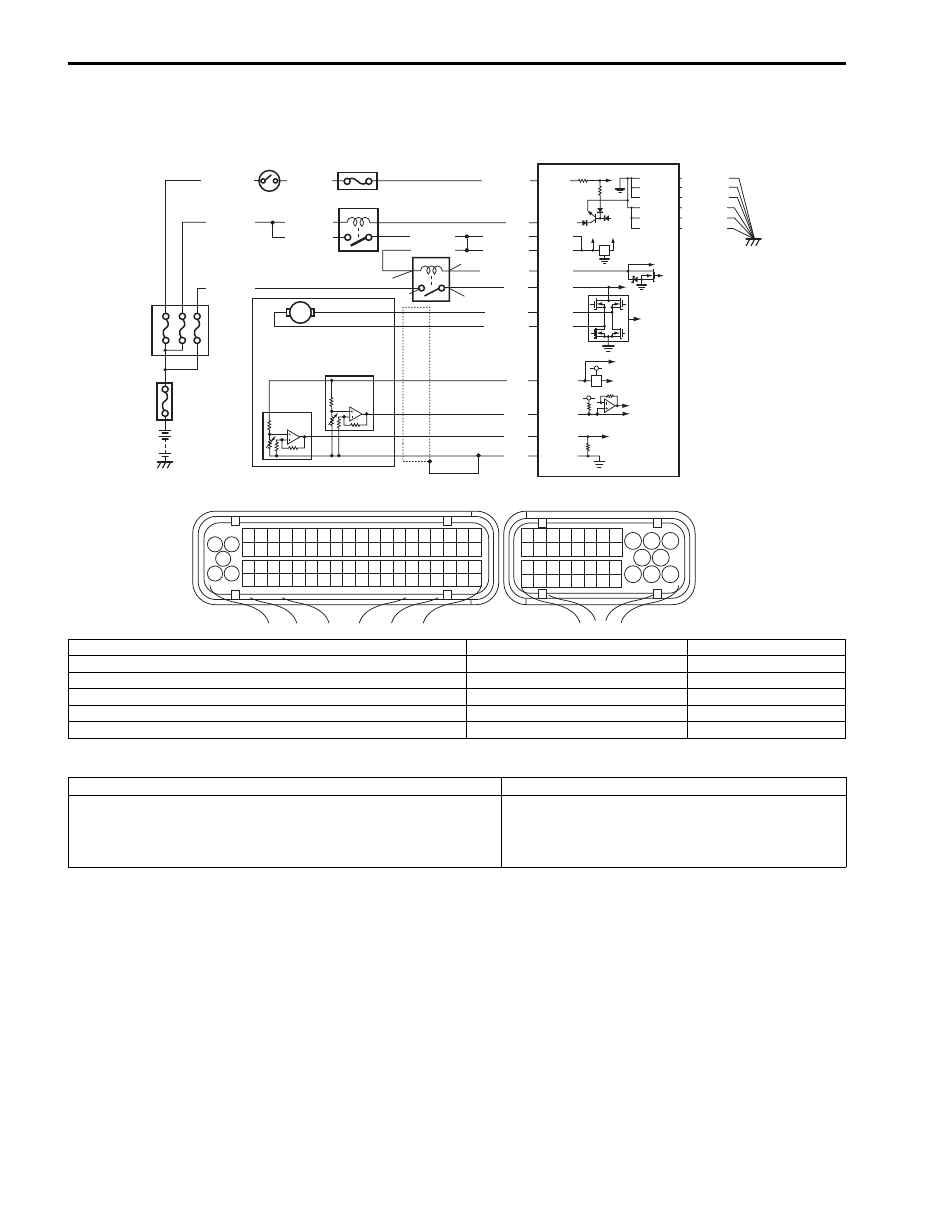
DTC P2102: Throttle Actuator Control Motor Circuit Low
S6JB0B1104059
Wiring Diagram
DTC Detecting Condition and Trouble Area
DTC Confirmation Procedure
1) With ignition switch turned OFF, connect scan tool.
2) Turn ON ignition switch and clear DTC by using scan tool if any.
3) Keep ignition switch is at ON position for 5 seconds or longer.
4) Check DTC by using scan tool.
BLU/BLK
BLU/BLK
BLU/BLK
BLK/RED
BLK/RED
BLK/RED
BLU
12V 5V
E23-8
E23-16
E23-2
E23-3
WHT/GRN
C37-59
C37-58
C37-39
C37-73
C37-80
BLK/YEL
BLK/ORN
BLK/ORN
BLK/YEL
BLK/YEL
1
3 2
4
5
6
7
8
9
1110
12
13
14
15
16
17
18
19
20
17
18
19
20
21
22
23
24
25
26
27
28
29
30
31
33
34
35
36
37
38
39
40
32
1
2
3
4
5
6
7
8
9
10
11
12
13
14
15
16
21
22
23
24
25
26
27
28
29
30
31
32
33
34
35
36
37
38
39
40
41
42
43
44
45
46
47
48
49
50
51
52
53
54
55
56
57
58
59
60
61
62
63
64
65
66
67
68
69
70
71
72
73
74
75
76
77
78
79
80
81
E23
C37
BLK/ORN
C37-81
BLK/YEL
BLK/WHT
BLU/ORN
GRN
BLU/YEL
BLU/RED
BLU/BLK
E23-6
E23-7
E23-5
E23-4
C37-45
C37-46
C37-65
C37-64
BLU/RED
WHT
GRN
RED
BLK
8
11 10 9
13
12
7
5
2
1
4
3
6
C1
S1
S2
C2
I5JB0C110013-01
C1: Power supply circuit of throttle actuator control relay (coil side)
3: Throttle position sensor (main)
9: “THR MOT” fuse
C2: Control circuit of throttle actuator control relay (coil side)
4: Throttle position sensor (sub)
10: “FI” fuse
S1: Power supply circuit of throttle actuator control relay (switch side)
5: Throttle actuator control relay
11: “IGN” fuse
S2: Control circuit of throttle actuator control relay (switch side)
6: ECM
12: “IG COIL” fuse
1: Electric throttle body assembly
7: Main relay
13: Ignition switch
2: Throttle actuator
8: Fuse box No.2
DTC detecting condition
Trouble area
Power supply voltage of throttle actuator control circuit is lower
than 6 V for more than 0.5 sec. even if throttle actuator control
relay turned on.
(1 driving cycle detection logic)
• Throttle actuator control relay and its circuit
• ECM