Suzuki Grand Vitara JB627. Manual - part 33
1A-81 Engine General Information and Diagnosis:
DTC P0111: Intake Air Temperature Sensor Circuit Performance
S6JB0B1104021
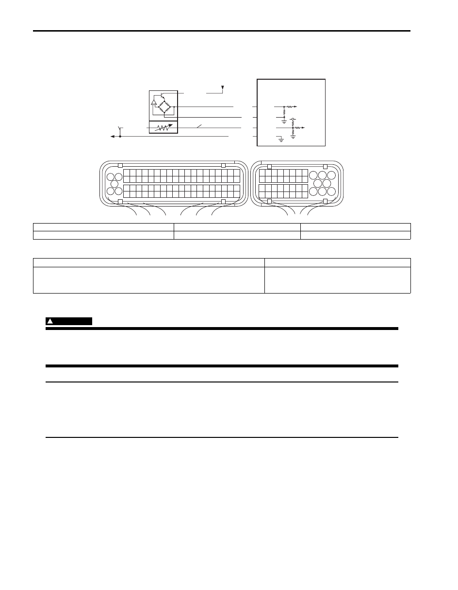
Wiring Diagram
DTC Detecting Condition and Trouble Area
DTC Confirmation Procedure
WARNING
!
• When performing a road test, select a place where there is no traffic or possibility of a traffic
accident and very careful during testing to avoid occurrence of an accident.
• Road test should be carried out with 2 persons, a driver and a tester, on a level road.
NOTE
Check to make sure that the following conditions are satisfied when using this “DTC Confirmation
Procedure”.
• Atmospheric pressure: higher than 75 kPa (560 mmHg) (Altitude: lower than 2790 m (9150 ft)).
• Engine coolant temperature at engine start: between –10
°C and 30 °C (14 °F and 86 °F).
• The following DTCs are not detected: MAF sensor, ECT sensor and IAT sensor (other than P0111).
1
3 2
4
5
6
7
8
9
1110
12
13
14
15
16
17
18
19
20
17
18
19
20
21
22
23
24
25
26
27
28
29
30
31
33
34
35
36
37
38
39
40
32
1
2
3
4
5
6
7
8
9
10
11
12
13
14
15
16
21
22
23
24
25
26
27
28
29
30
31
32
33
34
35
36
37
38
39
40
41
42
43
44
45
46
47
48
49
50
51
52
53
54
55
56
57
58
59
60
61
62
63
64
65
66
67
68
69
70
71
72
73
74
75
76
77
78
79
80
81
E23
C37
5V
GRY/GRN
GRY/GRN
BLU/BLK
BLU
RED
C37-23
C37-24
C37-67
C37-4
LT GRN
1
4
2
G
3
S
I6JB01110030-03
S: IAT sensor signal circuit
1. MAF and IAT sensor
3. To other sensors
G: IAT sensor ground circuit
2. ECM
4. From main relay
DTC detecting condition
Trouble area
Variation of IAT sensor signal is less than 15 mV even through ECT
reaches 75
°C after engine is started with ECT less than 30 °C.
(2 driving cycle detection logic)
• IAT sensor and its circuit
• ECM