Suzuki Grand Vitara JB416 / JB420. Manual - part 412
 

  Index      Suzuki     Suzuki Grand Vitara JB416 / JB420- service repair manual


Search            


Content   ..  410  411  412  413   ..


Suzuki Grand Vitara JB416 / JB420. Manual - part 412


10B-14 Body Electrical Control System: 

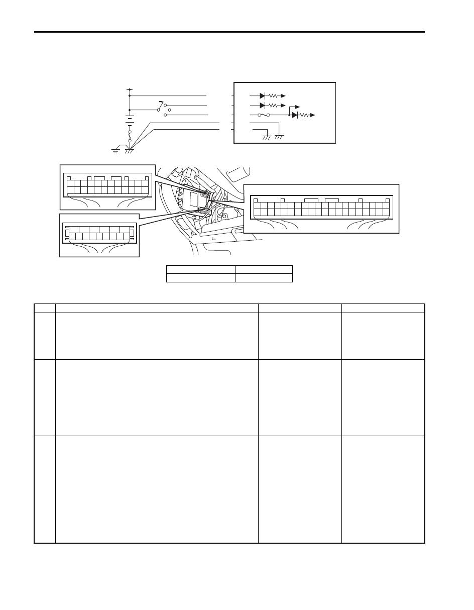
BCM Power Circuit and Ground Circuit Check

S5JB0AA204007

Wiring Diagram

Troubleshooting

7

8

9

10

11

12

13

14

15

6

5

4

3

2

1

G32

24

1

2

3

4

5

6

7

8

9

10

11

12

13

14

15

16

17

18

19

20

21

22

23

G30

1

2

3

4

5

6

7

8

9

10

11

12

13

14

15

16

17

18

19

20

21

22

23

24

25

26

27

28

29

30

31

32

33

34

35

36

37

38

39

40

G31

IG1

BLK
BLK

G32-1
G30-12

+B

G32-5

RED/WHT

WHT/BLK G30-2

PPL/RED G30-1

3

2

1

I5JB0AA20006-01

1. BCM

3. Battery

2. Ignition switch

Step

Action

Yes

No

1

Fuse check
1) Turn ignition switch to OFF position.
2) Check circuit fuses for condition.

Are circuit fuses in good condition?

Go to Step 2.

Replace fuse and check 
for short circuit to 
ground.

2

Power supply circuit check
1) Disconnect connectors from BCM.
2) Check for proper connection to BCM connector at 

terminal “G32-5”.

3) If OK, then measure voltage between “G32-5” terminal of 

BCM and vehicle body ground.

Is voltage 10 – 14 V?

Go to Step 3.

Repair power supply 
circuit.

3

Power supply circuit check
1) Check for proper connection to BCM connector at 

terminals “G30-1” and “G30-2”.

2) If OK, turn ignition switch ON.
3) Measure voltage between following terminals.

• Between “G30-1” terminal of BCM connector and 

vehicle body ground

• Between “G30-2” terminal of BCM connector and 

vehicle body ground

Is each voltage 10 – 14 V?

Go to Step 4.

Repair power supply 
circuit.

Body Electrical Control System:  10B-15

DTC B1133 (No. 1133): Battery Voltage Too High

S5JB0AA204008

Wiring Diagram

DTC Detecting Condition and Possible cause

Flow Test Description
Step 1: Check charging system

DTC troubleshooting

4

Ground circuit check
1) Turn ignition switch to OFF position.
2) Check for proper connection to BCM connector at 

terminals “G30-12” and “G32-1”.

3) If OK, then measure resistance between following 

terminals.
• Between “G30-12” terminal of BCM connector and 

vehicle body ground

• Between “G32-1” terminal of BCM connector and 

vehicle body ground

Is each resistance 2 

 or less?

BCM power supply 
circuit and ground circuit 
are in good condition.

Repair ground circuit.

Step

Action

Yes

No

7

8

9

10

11

12

13

14

15

6

5

4

3

2

1

G32

24

1

2

3

4

5

6

7

8

9

10

11

12

13

14

15

16

17

18

19

20

21

22

23

G30

1

2

3

4

5

6

7

8

9

10

11

12

13

14

15

16

17

18

19

20

21

22

23

24

25

26

27

28

29

30

31

32

33

34

35

36

37

38

39

40

G31

IG1

BLK
BLK

G32-1
G30-12

+B

G32-5

RED/WHT

WHT/BLK G30-2

PPL/RED G30-1

3

2

1

I5JB0AA20006-01

1. BCM

3. Battery

2. Ignition switch

DTC detecting condition

Possible cause

Power voltage supplied from battery to BCM is 
higher than 16V.

• Charging system malfunction
• BCM malfunction

Step

Action

Yes

No

1

Charging system operation check
1) Check generator for operation referring to “Generator 

Test (Overcharged Battery Check) in Section 1J”.

Is it in good condition?

Substitute a known-
good BCM and recheck.

Repair charging system.

10B-16 Body Electrical Control System: 

DTC B1141 / B1142 / B1143 (No. 1141 / No. 1142/ No. 1143): Outside Air Temperature (Ambient Temp.) 
Sensor Circuit Malfunction

S5JB0AA204009

Wiring Diagram

DTC Detecting Condition and Possible Cause

Flow Test Description
Step 1: Check whether malfunction is in outside air temperature sensor.
Step 2: Check outside air temperature sensor input circuit.
Step 3: Check outside air temperature sensor ground circuit (for DTC B1141 and B1143).

7

8

9

10

11

12

13

14

15

6

5

4

3

2

1

G32

24

1

2

3

4

5

6

7

8

9

10

11

12

13

14

15

16

17

18

19

20

21

22

23

G30

1

2

3

4

5

6

7

8

9

10

11

12

13

14

15

16

17

18

19

20

21

22

23

24

25

26

27

28

29

30

31

32

33

34

35

36

37

38

39

40

G31

WHT/BLK

BLK/RED

5V

G31-24

G31-21

1

2

2

3

1

I5JB0AA20007-01

1. Outside air temperature sensor

3. Outside air temperature sensor connector

2. BCM

DTC detecting condition

Possible cause

DTC B1141 (DTC No. 1141):
Input signal from outside air temperature sensor is higher 
than 4.88 V.

• Open in outside air temperature sensor circuit
• Outside air temperature sensor malfunction
• BCM malfunction

DTC B1142 (DTC No. 1142):
Input signal from outside air temperature sensor is lower 
than 0.1 V.

• Short in outside air temperature sensor circuit
• Outside air temperature sensor malfunction
• BCM malfunction

DTC B1143 (DTC No. 1143):
Input signal from outside air temperature sensor is 0.1 - 
0.27 V or 4.6 - 4.88 V.

• High resistance in outside air temperature sensor 

circuit

• Outside air temperature sensor malfunction
• BCM malfunction

Body Electrical Control System:  10B-17

DTC troubleshooting

DTC B1150 (No. 1150): Air Bag Communication Circuit Malfunction

S5JB0AA204010

Wiring Diagram

Step

Action

Yes

No

1

Check outside air temperature sensor
1) Turn ignition switch to OFF position.
2) Disconnect connector from outside air temperature 

sensor.

3) Check outside air temperature sensor for resistance 

referring to “Outside Air Temperature Sensor Inspection 
(If Equipped) in Section 9C”.

Is it in good condition?

Go to Step 2.

Replace outside air 
temperature sensor.

2

Check outside air temperature sensor circuit
1) Turn ignition switch to ON position.
2) Measure voltage between “WHT/BLK” terminal of 

outside air temperature sensor connector and vehicle 
body ground.

Is voltage 4 – 6 V?

Go to Step 3.

Open or short in “WHT/
BLK” circuit. If OK, 
substitute a known-
good BCM and recheck.

3

Check outside air temperature sensor circuit
1) Turn ignition switch to OFF position.
2) Check for proper connection to “G31-21” terminal of 

BCM connector.

3) If OK, measure resistance between “BLK/RED” terminal 

of outside air temperature sensor connector and vehicle 
body ground.

Is resistance 1 

 or less?

Substitute a known-
good BCM and recheck.

Open or high resistance 
in “BLK/RED” circuit.

7

8

9

10

11

12

13

14

15

6

5

4

3

2

1

G32

24

1

2

3

4

5

6

7

8

9

10

11

12

13

14

15

16

17

18

19

20

21

22

23

G30

1

2

3

4

5

6

7

8

9

10

11

12

13

14

15

16

17

18

19

20

21

22

23

24

25

26

27

28

29

30

31

32

33

34

35

36

37

38

39

40

G31

YEL

5V

G30-19

[A]: G47-22
[B]: G46-15

[A]

[B]

2

1

1

1

G46

G47

I5JB0AA20008-01

[A]: Vehicle not equipped with side-air bag

1. SDM

[B]: Vehicle equipped with side-air bag

2. BCM


Content   ..  410  411  412  413   ..