Suzuki: Engine K6A-YH6. Manual - part 22
7-42
REPAIR
7
Figure 7-97
NOTE
Apply clean oil to the connecting rod cap bearing and
crankshaft journal.
9.
Install connecting rod cap (17) and nuts (18). Tighten
to specification.
Connecting Rod Torque: 24 lb-ft (33 N•m)
10. Install crankshaft baffle. (See “Crankshaft Baffle” on
11. Install oil pump pickup. (See “Oil Pump Pickup” on
12. Install oil pan. (See “Oil Pan” on page 7-30.)
13. Install cylinder head. (See “Cylinder Head” on
Lower Crankcase, Cylinder Block,
and Crankshaft
Disassembly
See Figures 7-98 through 7-101.
1.
Remove cylinder head. (See “Cylinder Head” on
page 7-24.)
2.
Remove oil pan. (See “Oil Pan” on page 7-30.)
3.
Remove oil pump pickup. (See “Oil Pump Pickup” on
page 7-31.)
4.
Remove crankshaft baffle. (See “Crankshaft Baffle”
on page 7-32.)
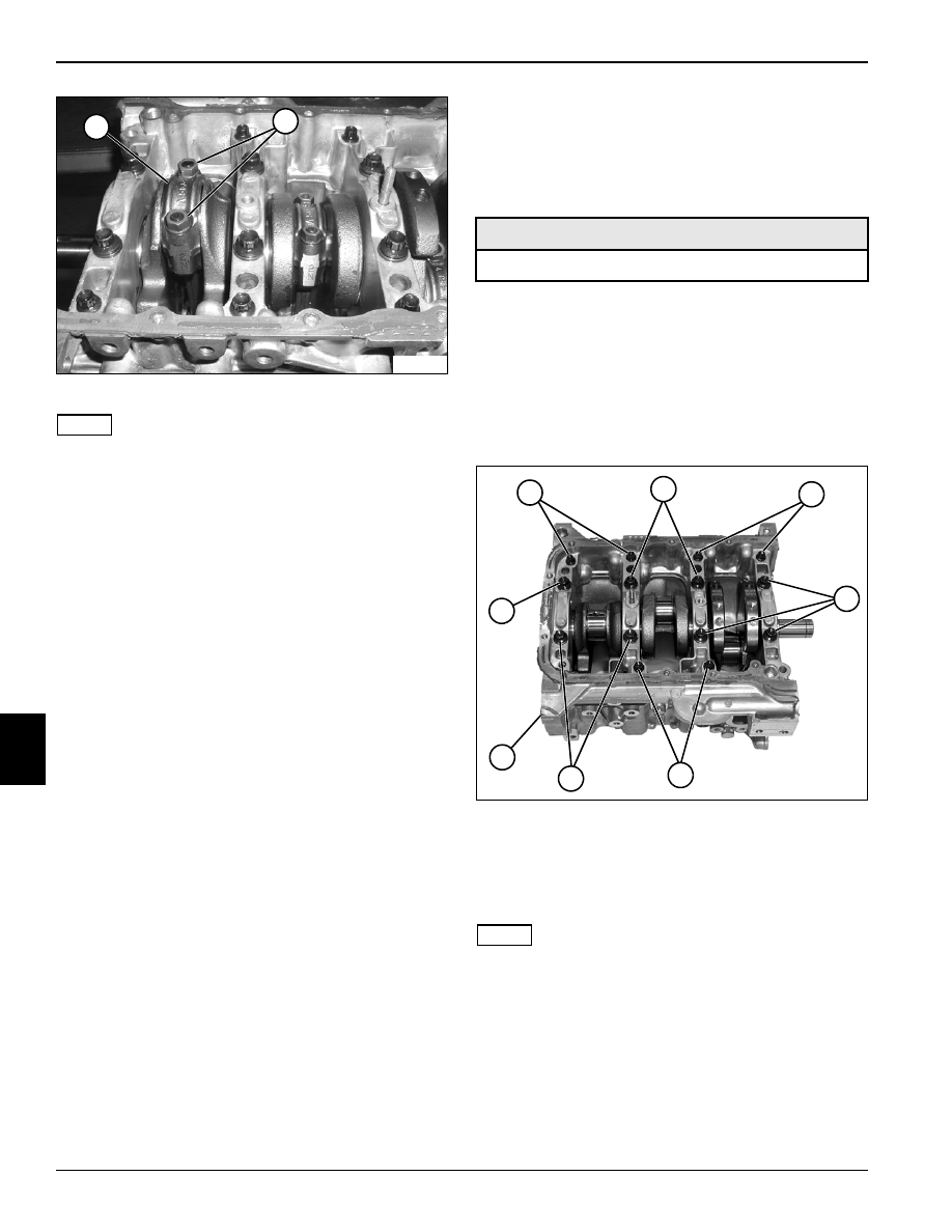
Figure 7-98
5.
Using a 12-point 8 mm socket, remove six screws
and washers (1).
6.
Using a 12-point 10 mm socket, remove eight screws
and washers (2).
NOTE
The lower crankcase is located using four dowel pins and
is sealed to the cylinder block using Three Bond ™ 1215
sealant. The lower crankcase must be lifted off square.
7.
Use a soft face mallet to loosen lower crankcase (3)
from cylinder block. Remove lower crankcase from
cylinder block. Be sure to lift lower crankcase off
square.
TN0752
17
18
Required Tools
8 and 10 mm 12-point sockets
TN0755
1
1
2
2
1
2
3
2