Subaru Ascent (2023 year). Manual in english - page 11
306 Overhead console
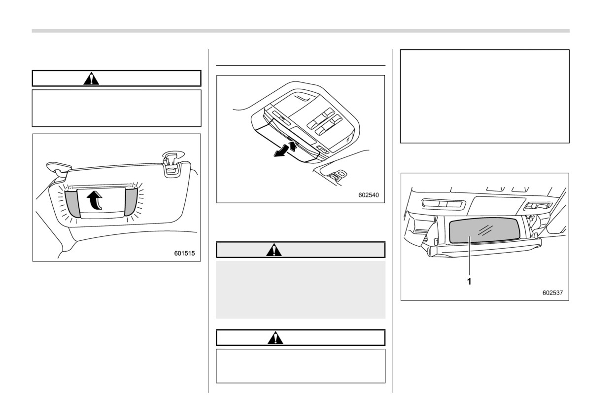
& Vanity mirror with light
6-4. Overhead console
heats up. Avoid storing plastic or
other heat vulnerable or flam-
CAUTION
mable articles such as a lighter
in the overhead console.
Keep the vanity mirror cover closed
. Do not pull the lid when opening
while the car is being driven to avoid
the overhead console.
being blinded by glare.
There is the risk that the over-
head console may be damaged.
& Cabin view mirror
To open the console, push up the lid lightly
that is located on the “PUSH” mark and it
will automatically open.
WARNING
To use the vanity mirror, swing down the
Do not use the overhead console
sun visor and open the vanity mirror cover.
while driving. Doing so may distract
you from the road conditions ahead
The lights beside the vanity mirror illumi-
and cause an accident that may
nate when the mirror cover is opened.
result in serious injury or death.
1
Cabin view mirror
NOTE
To use the cabin view mirror, push up the
Use of the vanity mirror light for a long
“PUSH” mark located on the lid lightly and
CAUTION
period of time while the engine is not
it will automatically open.
running can cause battery discharge.
. When your vehicle is parked in
the sun or on a warm day, the
inside of the overhead console
Storage compartment
307
6-5. Storage compartment
& Glove box
CAUTION
Always keep the storage com-
partment closed while driving to
reduce the risk of injury in the
event of a sudden stop or an
accident.
Do not store spray cans, contain-
ers with flammable or corrosive
liquids or any other dangerous
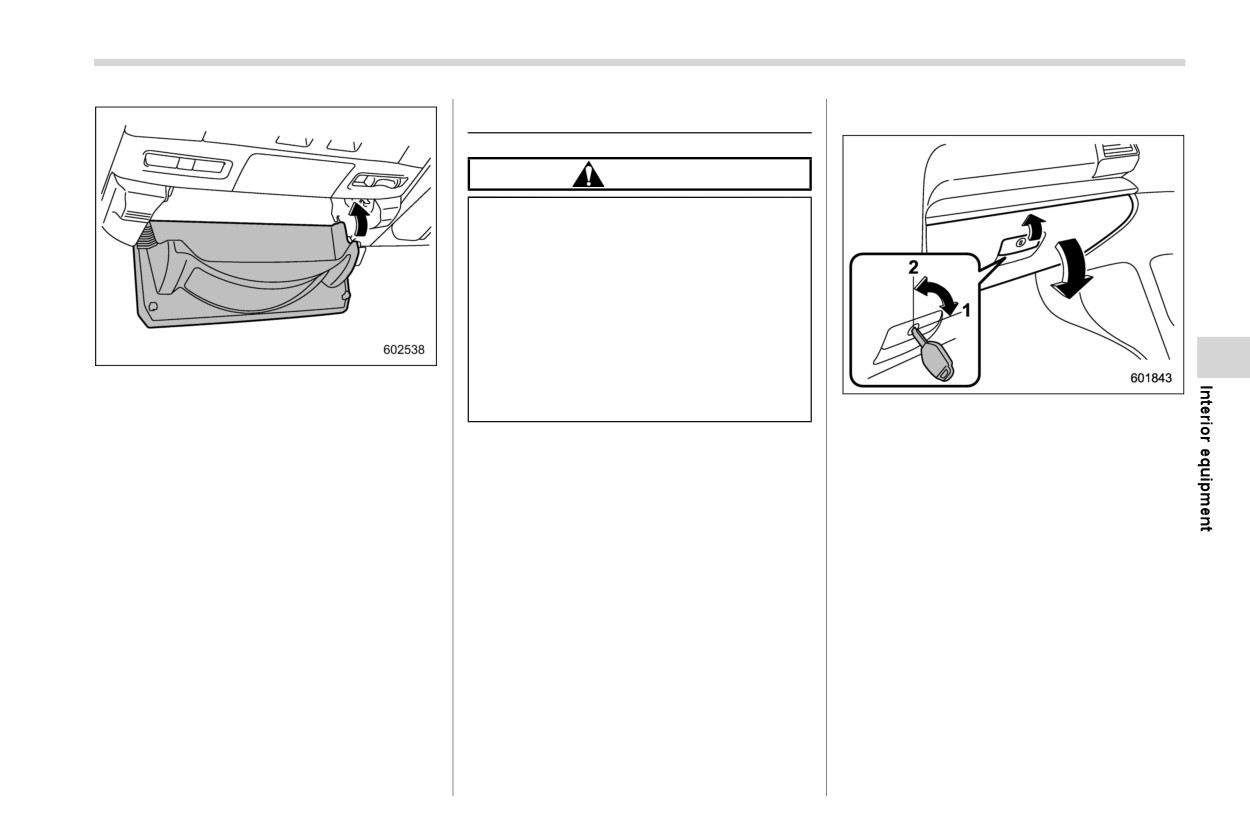
Push the lid back up half way.
items
in
the
storage
compart-
ment.
1
Rotate the key clockwise to lock.
NOTE
2
Rotate the key counterclockwise to un-
When opening the overhead console
lock.
while the cabin view mirror is in use,
To open the glove box, pull the handle.
first close the lid and then push up the
To close it, push the lid firmly upward.
“PUSH” mark to open the console.
NOTE
. The emergency key is directional. If
the key cannot be inserted, change
the direction that the grooved side is
facing and insert it again.
. For models with the “keyless access
with push-button start system”, use
the emergency key to lock or unlock
the glove box.
- CONTINUED -
308 Storage compartment
& Center console
Take care to avoid spills. Bev-
erages, if hot, might scald you
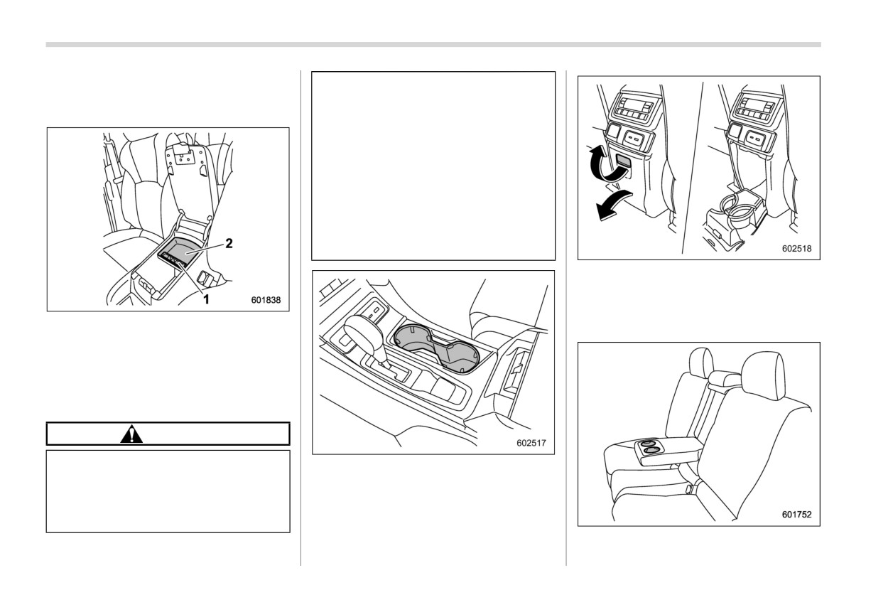
The center console box provides a storage
and/or your passengers. Spilled
space.
beverages may also damage up-
holstery or carpets.
When a cup in the rear passen-
ger’s cup holder contains a bev-
erage, do not fold down the rear
seatback. Otherwise, the bever-
age could spill and, if the bev-
erage is hot, it could scald you
and/or your passengers.
2nd-row seat’s cup holder (2nd-row cap-
tain seat models)
The cup holder is built into the center
console. To use the cup holder, pull the cup
1
Coin tray
holder lid.
2
Accessory tray
The top of the console can be used as an
armrest.
& Cup holders
CAUTION
. Do not pick up a cup from the cup
Front passenger’s cup holder
holder or put a cup in the holder
The cup holder is built into
the
center
while you are driving, as this may
console.
distract you and lead to an acci-
dent.
2nd-row seat’s cup holder (2nd-row bench
seat models)
Storage compartment
309
The cup holder is built into the armrest.
& Bottle holders
CAUTION
. Do not pick up a bottle from the
bottle holder or put a bottle in the
holder while you are driving, as
this may distract you and lead to
an accident.
. When placing a beverage in a
bottle holder, make sure it is
capped. Otherwise, the beverage
could spill when opening/closing
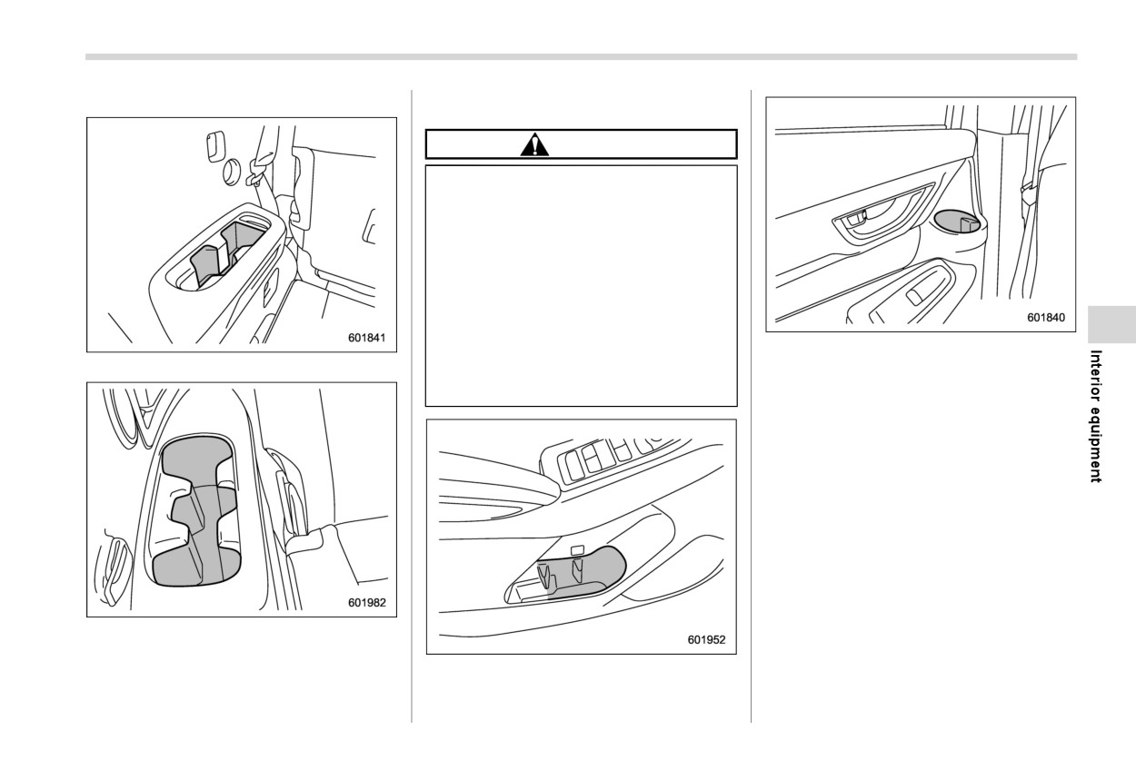
Rear door bottle holder
the door or while driving and, if
3rd-row seat’s cup holder (left side)
the beverage is hot, it could scald
The bottle holder equipped on each door
you and/or your passengers.
trim can be used to hold beverage bottles
and other items.
3rd-row seat’s cup holder (right side)
The cup holder is built into the rear side
Front door bottle holder
trim.
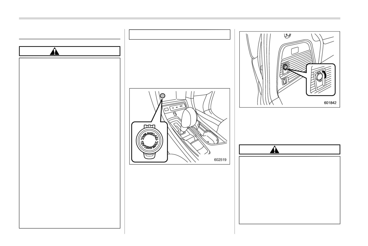
310 Power outlets
6-6. Power outlets
driving.
CAUTION
& 12 V power outlet
Electrical power (12 V DC) is available at
Do not place any foreign objects,
any of the accessory power outlets when
especially metal ones, such as
the ignition switch is in either the “ACC” or
coins or aluminum foil, into the
“ON” position. Accessory
power outlets
accessory power outlet. That
are located in the following places.
could cause a short circuit. Al-
ways put the cap on the acces-
sory power outlet when it is not in
use.
If the plug on your electric appli-
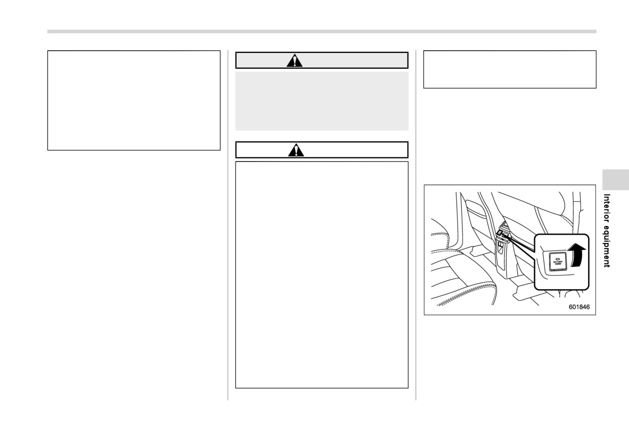
Power outlet in the cargo area
ance is either too loose or too
You can use an in-vehicle electrical appli-
tight for the accessory power
ance by connecting it to an outlet.
outlet, this can result in a poor
The maximum power rating of an appli-
contact or cause the plug to get
ance that can be connected is 120 W.
stuck. Only use plugs that fit
properly.
CAUTION
Use of an electric appliance in the
. Do not attempt to use a cigarette
accessory power outlet for a long
lighter in the accessory power
period of time while the engine is
Power outlet
outlets.
not running can cause battery
discharge.
. Use only electrical appliances
which are designed for 12 V DC.
Before driving your vehicle, make
sure that the plug and the cord on
The maximum power rating of an
your electrical appliance will not
appliance that can be connected
interfere with shifting gears and
is 120 W. Do not use an appliance
operating the accelerator and
which exceeds the indicated wat-
brake pedals. If they do, do not
tage for each outlet.
use the electrical appliance while
Power outlets
311
. When using appliances con-
so may cause the plug to stick
WARNING
nected to two outlets simulta-
and overheat, creating a potential
neously, the total power con-
To avoid being burned, never grasp
fire hazard.
sumed by them must not exceed
the lighter by the end with the
120 W. Overloading the acces-
heating element. Doing so could
sory power outlet can cause a
result in injury and could also da-
& 120 V power outlet (if
short circuit. Do not use double
mage the heating element.
equipped)
adapters or more than one elec-
Electrical power (120 V AC) is available at
trical appliance.
any of the power outlets when the ignition
CAUTION
switch is in either the
“ACC” or
“ON”
Do not hold the lighter pushed in,
position. Power outlets are located in the
& Use with the cigarette lighter
because it will overheat.
following places.
(dealer option)
The electrical power socket is
To use the accessory power outlet as a
originally designed to use a gen-
cigarette lighter socket, purchase the
uine SUBARU cigarette lighter
cigarette lighter plug, which is an optional
plug. Do not use a non-genuine
accessory. A cigarette lighter plug is
cigarette lighter plug in the sock-
available from your SUBARU dealer.
et. Doing so may cause a short-
The cigarette lighter operates only when
circuit and overheating, resulting
the ignition switch is in the “ON” or “ACC”
in a fire.
position.
If the socket is ever used for a
To use the cigarette lighter, push in the
plug-in accessory such as a cell
knob and wait a few moments. It will
phone, that may damage the
automatically spring up when ready for
portion of the socket’s internal
use.
mechanism that causes a cigar-
Power outlet behind the center console
ette lighter plug to “pop out” after
The maximum power rating of an appli-
its lighter element is heated.
ance that can be connected is 100 W.
Therefore, do not place a cigar-
ette lighter plug in a socket that
has been used, even once, to
power a plug-in accessory. Doing
- CONTINUED -
312 USB power supply
CAUTION
6-7. USB power supply
If a device is connected for a long
time when the engine is not
Use only electrical appliances
running, the battery may be dis-
which are designed for 120 V
CAUTION
charged. Even when the engine is
AC. The maximum power rating
running, we recommend that you
The specification of a USB term-
of an appliance that can be con-
do not connect a device for an
inal that can be used is the Type-
nected is 100 W. Do not use an
unnecessarily long time.
A and Type-C. If a different spe-
appliance which exceeds the in-
Do not connect a malfunctioning
cification of terminal is con-
dicated wattage for each outlet.
device. Doing so may cause
nected, power supply or charging
The maximum power rating of an
smoke and fire.
may not be possible, or the
appliance that can be connected
device may malfunction.
Remove the USB electronic de-
is 100 W. Do not use an appliance
vice from the console USB power
which exceeds the indicated wat-
There is a risk that a connected
supply before operating the sec-
tage for each outlet.
device may malfunction or data
ond-row seat slide. There is a risk
may be damaged. The connec-
When using appliances con-
that the USB power supply or
tion of a device shall be per-
nected to two outlets simulta-
USB electronic device may be
formed at your responsibility.
neously, the total power con-
damaged.
sumed by them must not exceed
To avoid an electric shock or a
Put the cap on the 3rd-row seat
100 W. Overloading the acces-
malfunction, observe the follow-
USB terminal when it is not in
sory power outlet can cause a
ing precautions.
use. If any foreign objects get
short circuit. Do not use double
- Do not connect a USB hub.
into the USB terminal, that could
adapters or more than one elec-
- Do not insert any metal or
cause a short circuit.
trical appliance.
other foreign objects into the
Remove the plug from the power
USB terminal.
outlet before operating the sec-
NOTE
- Do not spill water or other
ond-row seat slide. There is a risk
. The rated voltage of each USB
liquid on the USB terminal.
that the 120 V power outlet or
terminal is DC 5 V. For details about
plug may be damaged.
Be careful not to pull the con-
the maximum rated power, refer to
nected cable. Doing so could
“How to use the USB power supply”
break the USB terminal and the
FP313. Before connecting a device,
connected device.
be sure to read the instruction
manual of the device and check
USB power supply
313
whether or not this specification of
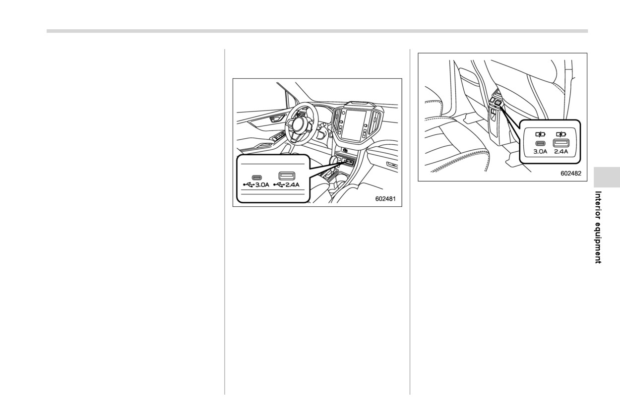
& How to use the USB power
the output is supported by the
supply
device. If a device that requires
power exceeding the maximum rat-
ing is connected, power supply or
charging may not be possible. Even
if charging could be completed, the
time required for charging may be
longer than when the genuine char-
ger for that device is used.
Depending on the device, charging
may be possible only when a special
cable is used. In this case, be sure to
connect the device using the special
Console USB power supply (power supply
cable.
function only)
When a device that communicates
- USB Type-A: DC 5 V/2.4 A*
Front seat USB power supply (an audio
with a PC is connected, power
device can be connected and used)
- USB Type-C: DC 5 V/3.0 A*
supply or charging may not be
2-terminal type USB power supply
possible.
*: The available electrical power of the two USB
- USB Type-A: DC 5 V/2.4 A*
When connect a device for charging,
terminals is a maximum of 5.4 A.
disconnect the device promptly after
- USB Type-C: DC 5 V/3.0 A*
charging is completed.
*: The available electrical power of the two USB
terminals is a maximum of 5.4 A.
1-terminal type USB power supply
- USB Type-A: DC 5 V/2.4 A
- CONTINUED -
314 Ashtray (dealer option)
6-8. Ashtray (dealer option)
CAUTION
Do not use ashtrays as waste
receptacles or leave a lighted
cigarette in an ashtray. This could
cause a fire.
Always extinguish matches and
cigarettes before putting them
into the ashtray, and then close
the ashtray securely. If you keep
3rd-row seat USB power supply (power
the ashtray open, the fire of the
The portable ashtray can be installed in
supply function only) (if equipped)
cigarette may spread to another
each cup holder or bottle holder. For the
- USB Type-A: DC 5 V/2.1 A*
cigarette butt and start a fire.
locations of the cup holders, refer to “Cup
holders” FP308. For the locations of the
Do not put flammable material in
*: The available electrical power of the two USB
bottle holders, refer to
“Bottle holders”
the ashtray.
terminals is a maximum of 4.2 A.
FP309.
Do not leave a lot of cigarette
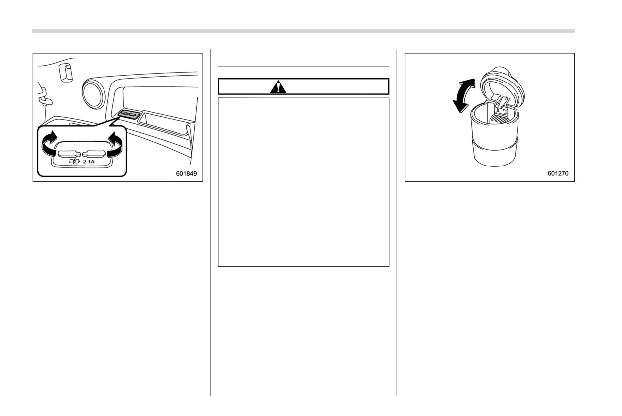
Use the USB terminal to use or charge an
butts in the ashtray.
When using the ashtray, open the lid of the
electronic device.
ashtray. Fully close the lid after using the
When using the terminal, open the USB
ashtray to help reduce residual smoke.
power supply cover. After use, close the
NOTE
USB power supply cover.
Particles of ash and tobacco will accu-
When the ignition switch is in the “ACC” or
mulate around the hinges of the ash-
“ON” position, the power can be supplied
tray’s inner lid. Clean them off using a
to the electronic device.
toothbrush or a similar narrow-ended
implement.
Floor mat
315
6-9. Floor mat
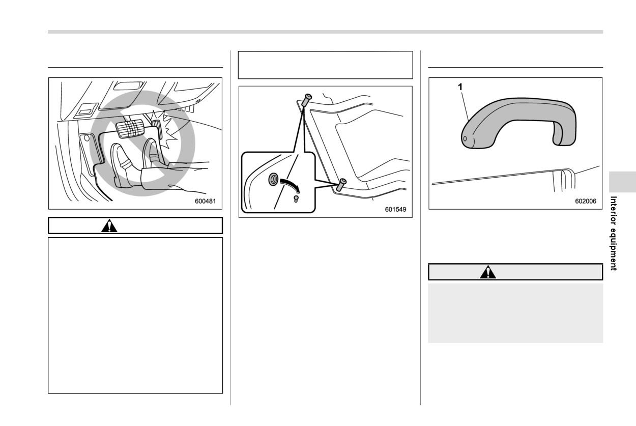
. Do not use more than one floor
6-10. Assist grip
mat.
1
Assist grip
CAUTION
Retaining pins are located on the driver’s
The assist grip is to be held to support the
side floor.
body of the passengers when they are in
If the floor mat slips forward and
The floor mat should be properly secured
the seat and the vehicle is moving.
interferes with the movement of the
using the built-in grommets, by placing the
pedals during driving, it could cause
grommets over the pins and pushing them
WARNING
an accident. Observe the following
downward.
precautions to prevent the floor mat
Do not hold the assist grip when
from slipping forward.
getting up from the seat. Holding
. Be sure to use a genuine
and pulling the assist grip in the
SUBARU floor mat or an equiva-
wrong way could break the grip and
lent designed with grommets in
possibly cause injury.
the correct locations.
. Make sure that the driver’s floor
mat is placed in its proper loca-
tion and is correctly secured on
its retaining pins.
- CONTINUED -
316 Coat hook
CAUTION
6-11. Coat hook
WARNING
Do not attach heavy objects to the
Obey the following instructions.
assist grip. Doing so could break it
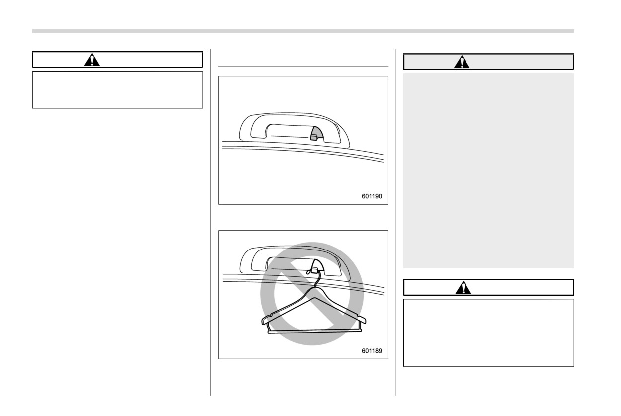
. Do not hang coat hangers or
and damage the object.
other hard or pointed objects on
the coat hooks. Hang clothing
directly on the coat hooks with-
out using hangers.
. Before hanging clothing on the
coat hooks, make sure there are
no pointed objects in the pock-
ets.
If these instructions are ignored, the
following may occur in sudden
A coat hook is attached
to
the
rear
stops or in a collision.
passenger’s assist grip.
. Serious injuries by the items
thrown through the cabin
. Incorrect SRS curtain airbag de-
ployment
CAUTION
Never hang anything on the coat
hook that might obstruct the driver’s
view or that could cause injury in
sudden stops or in a collision. And
do not hang items on the coat hook
that weigh 11 lbs (5 kg) or more.
Shopping bag hook
317
6-12. Shopping bag hook
6-13. Cargo area cover (if
WARNING
equipped)
Do not place anything on the ex-
CAUTION
tended cover. Putting excessive
The cargo area cover is provided for
weight on the extended cover can
covering the cargo area and to protect its
Do not hang items on the shopping
break it and an object on the cover
contents from direct sunlight. This cover is
bag hook that weigh 6 lbs (3 kg) or
could tumble forward in the event of
detachable to make room for additional
more.
a sudden stop or collision. This
cargo.
could cause serious injury.
& Using the cover
CAUTION
Be careful not to scratch the rear
gate stays while extending and re-
winding the cover.
Scratches on the stays could cause
leakage of gas from the stays, which
may result in their inability to hold
the rear gate open.
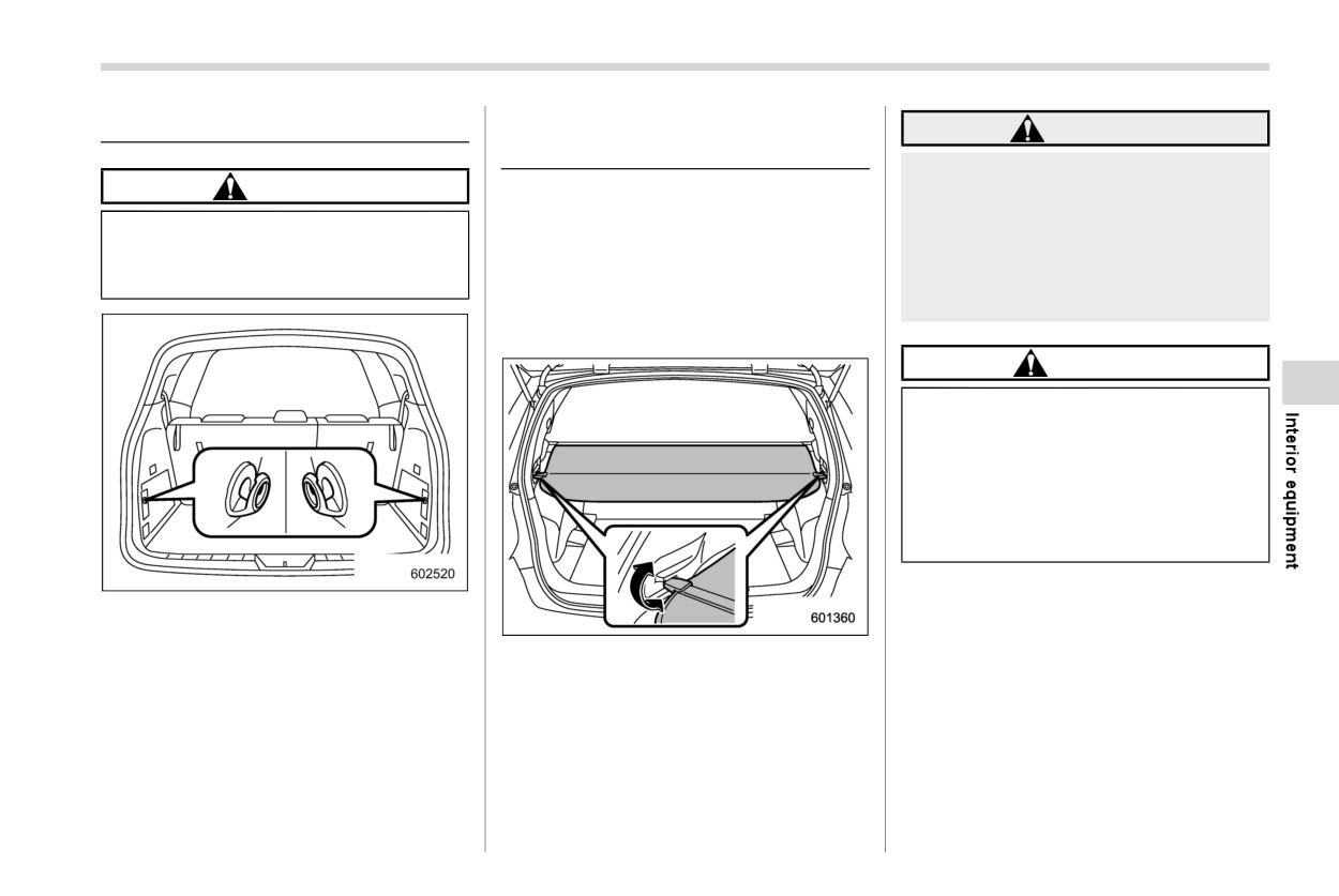
A shopping bag hook is attached to each
side of the cargo area.
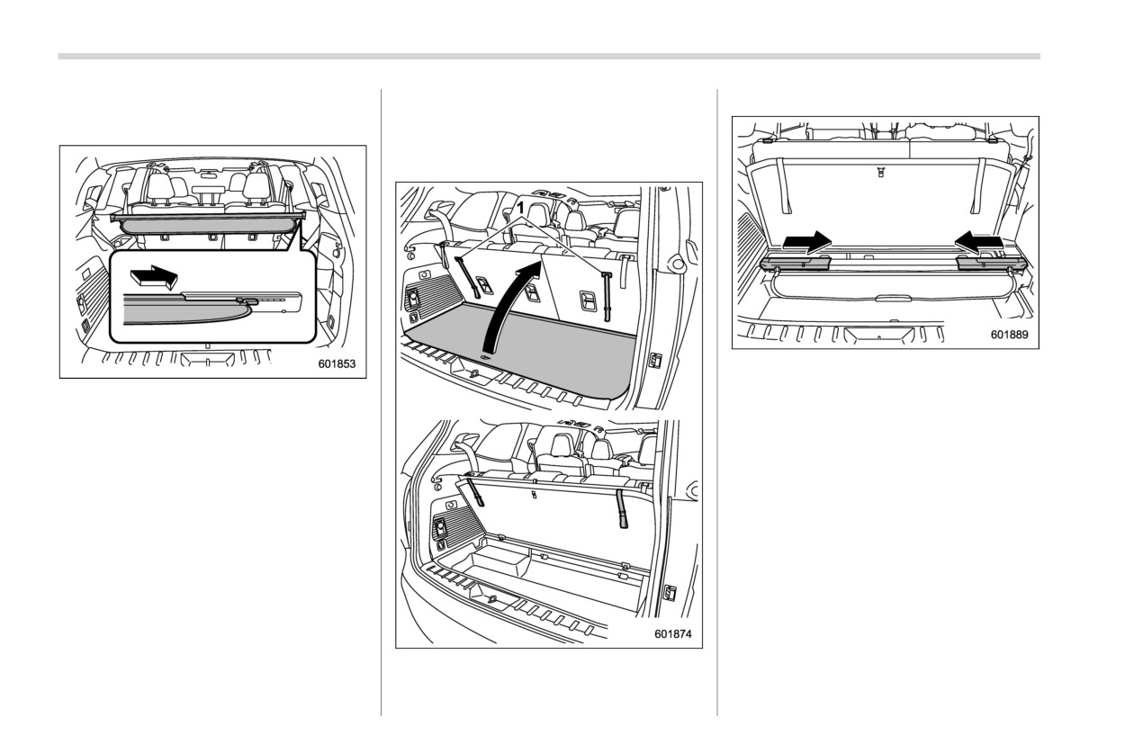
To extend the cover, pull the end of the
cover out of the housing, then insert its
hooks into the catches as shown. To
rewind it, unhook it from the catches and
it will rewind automatically. You should
hold on to the cover and guide it back into
the cover housing while it is rewinding.
- CONTINUED -
318 Cargo area cover
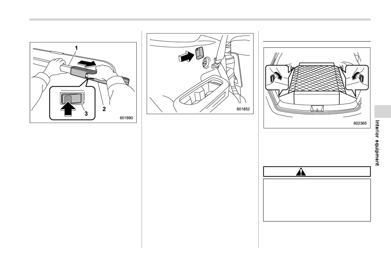
& To remove the cover housing
& Stowage of the cargo area
floor board.
cover
1. Rewind the cover.
The cargo area cover can be stowed in
under the cargo floor.
2. Shorten the cargo area cover, then
stow it under the cargo area floor.
2. Push the cover housing to the right, to
3. Put the cargo floor board back.
shorten the length of the cover.
3. Remove it from the retainer.
NOTE
To stow, insert the right end of the
cover into the recess of floor. To take it
out, lift up the left end of the cover, then
pull it out from the recess.
1
Straps
1. Raise and fold the rear end of the cargo
Cargo tie-down hooks
319
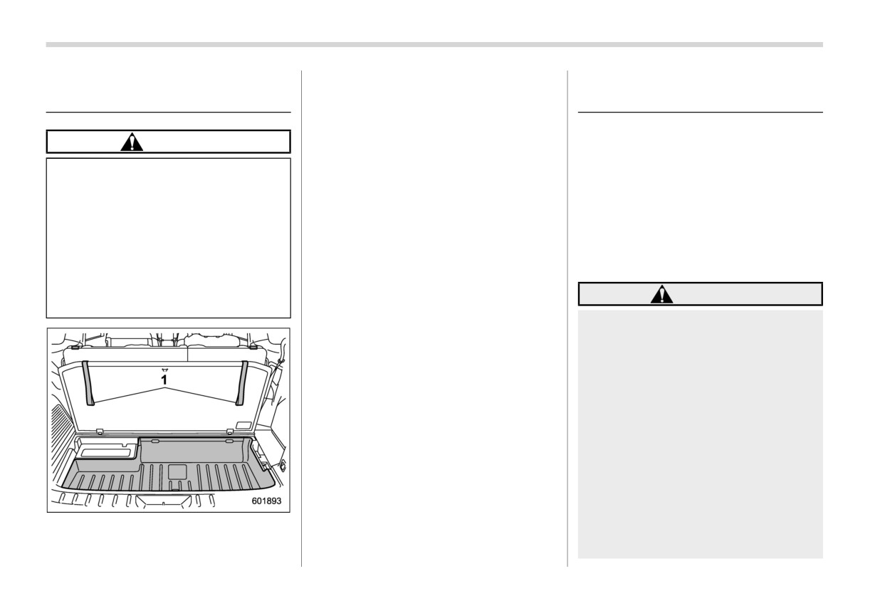
& To install the cover housing
6-14. Cargo tie-down hooks
3. Insert both ends of the cover housing
1
Cargo cover inner housing
into the recesses of the retainers.
2
Cargo cover outer housing
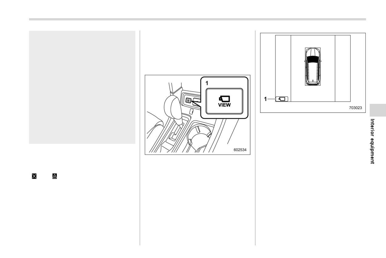
The cargo area is equipped with several
3
Cargo cover button
tie-down hooks so that cargo can be
NOTE
secured with a cargo net or ropes.
1. Hold the cover inner housing and outer
Store the window-side seatbelt in the
When using the tie-down hooks, turn them
housing. Press the cover housing
holder before using the cover housing.
down out of the storing recesses.
button and lengthen the cover housing.
2. Shorten the cover housing.
CAUTION
The cargo tie-down hooks are de-
signed only for securing light cargo.
Never try to secure cargo that ex-
ceeds the capacity of the hooks. The
maximum load capacity is 22 lbs (10
kg) per hook.
320 Under-floor storage compartment
The under-floor storage compartment is
6-15. Under-floor storage
6-16. Surround View Monitor
located under the floor of the cargo area
compartment
(if equipped)
and can be used to store small items. To
open the lid, pull the tab and keep the lid
Surround View Monitor is a feature that
CAUTION
using the strap on the seatback.
displays camera images on the center
Always keep the lid of the under-
information display to allow the driver to
floor storage compartment
check the blind spots of the vehicle. You
can use it to check the area in the front of
closed while driving to reduce
the vehicle, when starting the vehicle or
the risk of injury in the event of
while driving, and the area to the rear of the
sudden stop or an accident.
vehicle, when backing up. You can also
Do not store spray cans, contain-
use it to check your surroundings when
ers with flammable or corrosive
parking the vehicle.
liquids or any other dangerous
items in the under-floor storage
WARNING
compartment.
Never rely on only the Surround
View Monitor when driving the
vehicle. The image on the moni-
tor screen may appear different
from the vehicle’s actual sur-
roundings. If you drive the vehi-
cle by viewing only the monitor
image, a collision or an accident
may occur. When driving the
vehicle, always remain alert and
the check the surrounding traffic
directly and by using the mirrors.
Do not use the Surround View
Monitor in the following situa-
1
Straps
tions.
- You are driving on a dirt road
Surround View Monitor
321
or a road covered in snow.
& How to change the display of
– The camera malfunctions (e.g.
Surround View Monitor
the lens or bracket is broken).
When the ignition switch is in the “ON”
- The outside mirrors are re-
position, you can operate the select lever
tracted.
and the view monitor switch to display the
image on the Surround View Monitor.
- The front door is not fully
closed.
If the outside temperature is low,
the monitor screen may become
dark or the image may become
dim. In particular, the image of a
moving object may appear dis-
1
View icon
torted or disappear from the
screen. Always remain alert and
! Checking your surroundings while
check the surrounding traffic di-
the vehicle is stopped
rectly when driving.
To
display a
3D view of the vehicle’s
surroundings, press the view monitor
NOTE
switch when the select lever is in the “P”
1
View monitor switch
If there is a Surround View Monitor
position.
system malfunction, an error message
“
” or “
” is displayed on the center
information display. For details, refer to
“Malfunctions of the center information
display” FP467.
- CONTINUED -
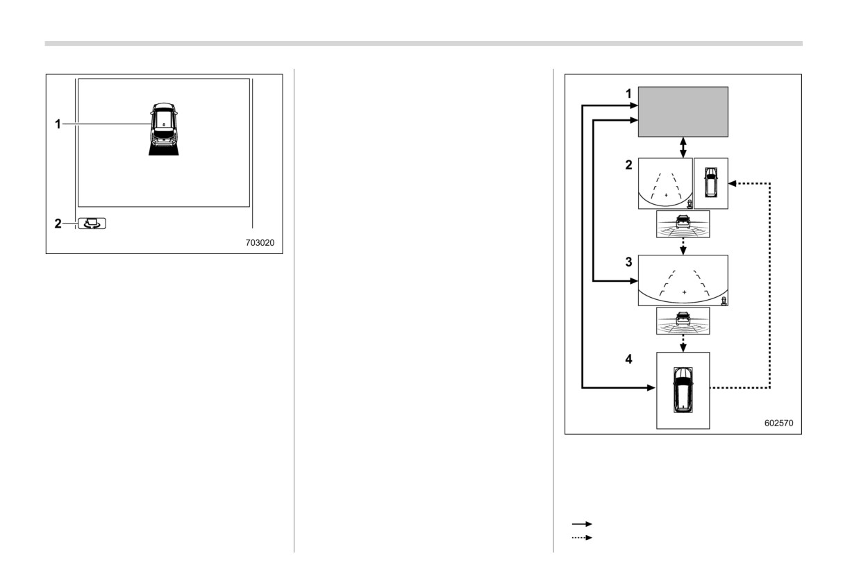
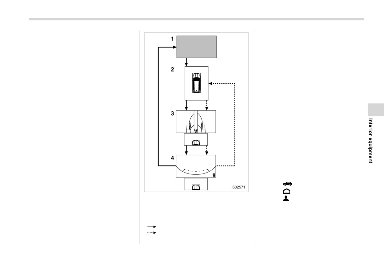
322 Surround View Monitor
! Checking the rearward
When the select lever is move to “R”, the
image in the rearward direction is dis-
played. Pressing the view monitor switch
or touching the view icon while the image
of the rear camera is displayed will switch
the screen view.
1
Vehicle icon
2
Vehicle angle icon
When the 3D view is displayed, the display
angle switches clockwise from the starting
position. When the view returns to the
starting position, the display angle stops
switching. You can also switch the display
angle by touching the vehicle angle icon on
the screen.
NOTE
If you turn off the Surround View
Monitor or change the screen to oper-
1
Original screen
ate other functions, the next time the
2
Rear view screen/Top view screen/Re-
image is displayed, it will be displayed
verse Automatic Braking (RAB) screen
at the previously displayed angle.
3
Rear view screen/Reverse Automatic
Braking (RAB) screen
4
Top view screen
: Shift the select lever.
: Touch the view icon or press the view
Surround View Monitor
323
monitor switch.
NOTE
If you turn off the Surround View
NOTE
Monitor or use it to operate another
If you turn off the Surround View
function, the next time the image is
Monitor or use it to operate another
displayed, the previously displayed
function, the next time the image is
screen will be shown.
displayed, the previously displayed
screen will be shown.
& How to cancel Surround View
When “Rear Camera Delay Control”
is on, the rear-view image will be
Monitor
displayed on the center information
There are several ways to cancel Sur-
display for a certain period of time
round View Monitor.
after the select lever is shifted from
! Manual cancellation
the “R” position to another position
(other than the “P” position). To turn
The Surround View Monitor will be can-
the function on and off, refer to
celed by either of the following operations.
“General settings” FP210.
. Press the view monitor switch until the
original screen is displayed (when the
! Checking the front
select lever is other than the
“R”
When the view monitor switch is pressed
position).
while the select lever is in the “N” or “D”
. Move the select lever to a position other
position, the front view is displayed.
than the “R” position (when the select
lever is in the “R” position).
. Touch
(car settings icon).
. Touch
(HOME).
1
Original screen
. Touch
(driver profiles icon).
2
Top view screen
! Automatic cancellation
3
Left-side view screen/Right-side
view
screen/Front-top view screen
If any of the following conditions are met,
4
Front view screen/Front-top view screen
the Surround View Monitor is canceled
: Press the view monitor switch.
automatically.
: Touch the view icon.
- CONTINUED -
324 Surround View Monitor
When the select lever is other than in
& How to view the camera
that provide information on the distance
the “R” position
images
and direction of travel of your vehicle, as
- About 3 minutes have elapsed since
well as information on any vehicles you are
you pressed the view monitor switch
approaching.
to access the Surround View Moni-
tor.
CAUTION
When the select lever is not in the “R” or
When you drive the vehicle, do
“P” position
not rely only on the guiding lines.
- The vehicle accelerates to 13 mph
Make sure that you check your
(20 km/h) or more.
surroundings directly.
- You depress the brake pedal and
The position and other informa-
pull up the parking brake switch to
tion provided by the guiding lines
apply the parking brake.
may differ from the actual dis-
When the select lever is in the “D” or “R”
tance of objects from the vehicle
position
if it is tilting at an angle relative to
- The select lever is shifted to the “P”
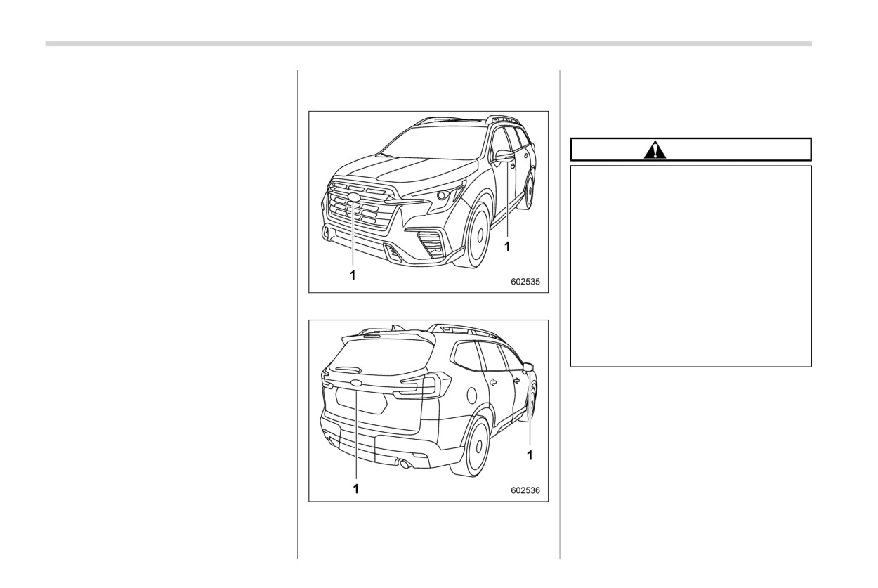
1
Cameras
the road surface due to the num-
position.
ber of passengers or the distribu-
tion of cargo on board the vehi-
cle.
NOTE
. Top view and rear view only: The
display of the predicted course line
linked to the steering angle can be
turned on/off by operating “Steering
Angle Lines” in the center informa-
tion display. To turn the function on
and off, refer to “General settings”
1
Cameras
FP210.
. The camera image may be hard to
The camera image displays guiding lines
see in the following situations. This
Surround View Monitor
325
is not a malfunction.
– When driving at night, the light
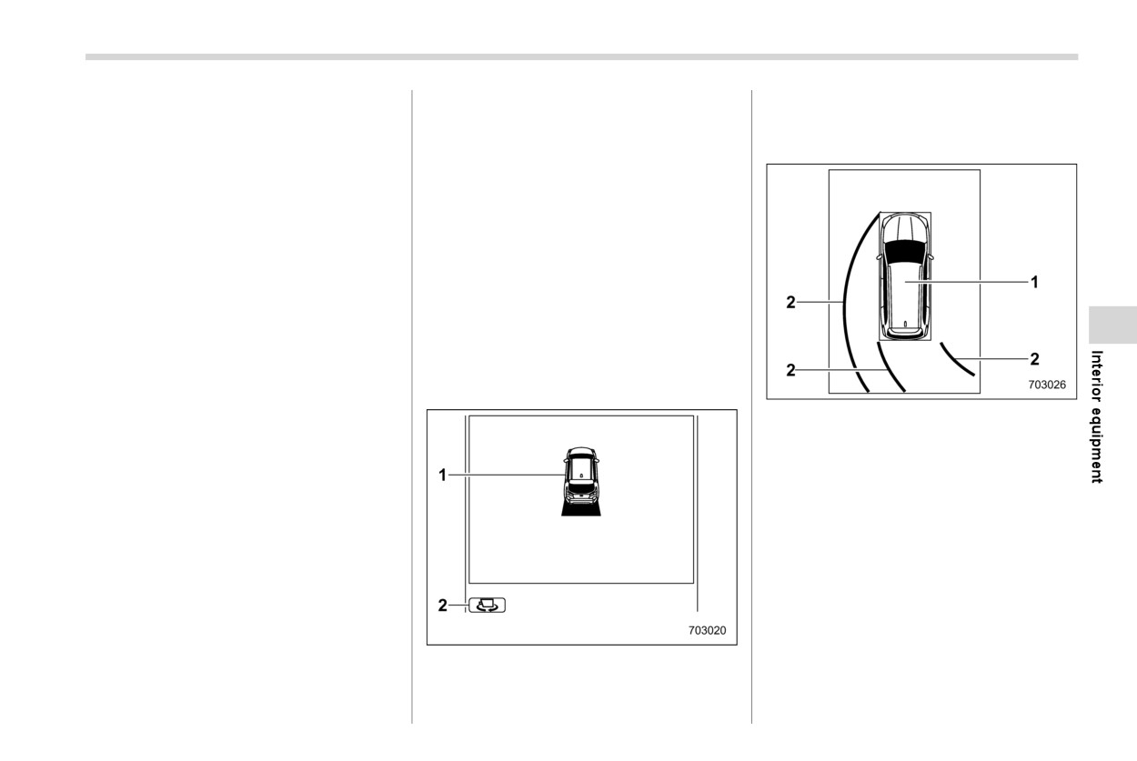
The 3D view displays the area around the
- Vehicle surroundings are dark
from a vehicle or building located
vehicle.
(such as at night).
ahead shines in the direction of
! Top view
- Ambient temperature outside the
the camera.
vehicle is high or low.
- When the vehicle is in a dark
- There is water or humidity on the
place or when driving at night, the
lens (such as in rainy weather).
camera image may be adjusted to
make image noise less visible.
- There is foreign material (such as
mud) on or near the camera.
Therefore, the image may look like a
- Sunlight or a headlight beam
monochromatic image or the image
shines directly shines toward
colors may differ from the actual col-
the camera lens.
ors. The image sharpness in the center
Under an artificial light such as a
and in the four corners of the screen
fluorescent lamp, sodium-vapor
may differ. This is not a malfunction.
lamp or mercury lamp, the lighted
portion may appear to flicker (flicker
!
3D view
phenomenon).
1
Vehicle icon
When the display is cold, the image
2
Predicted course line*
may leave traces or become darker
*: When the select lever is in the “R” position.
than usual, causing a difficulty in
The top view displays an image of the
viewing the screen. When driving
vehicle’s surroundings from above the
your vehicle, make sure that you
vehicle. This view is useful for checking
check your surroundings directly for
the vehicle’s surroundings when you are
traffic.
driving.
The following conditions may affect
the appearance of the screen, but
any resulting image distortion on the
screen does not indicate a malfunc-
tion.
- When humidity is high on a rainy
1
Vehicle icon
day, the camera lens becomes
2
Vehicle angle icon
foggy.
- CONTINUED -
326 Surround View Monitor
! Front view
! Side view
! Rear view
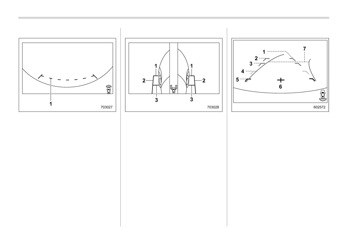
1
Guiding lines
1
Front-of-vehicle guiding line
1
Vehicle width line (oblique vertical line)
2
Side-of-vehicle guiding line
2
Approx. 10 ft (3 m) from the bumper
The guiding lines that indicate the width
3
Center-of-front-tire guiding line
(green horizontal line)
and the front end of your vehicle are
3
Approx. 6 ft (2 m) from the bumper (green
displayed on the monitor.
Guiding lines that indicate the width and
horizontal line)
the front end of the vehicle are displayed
4
Approx.
3 ft
(1
m) from the bumper
on the monitor.
(yellow horizontal line)
5
Approx. 1.5 ft (0.5 m) from the bumper
(red horizontal line)
6
Vehicle centerline
7
Dynamic guidelines
The help lines are a guide to help you
judge distances based on the screen
image.
Surround View Monitor
327
& Range of Surround View
motion and proceed slowly. If you do
Do not vigorously rub the camera
Monitor
not, it may cause an accident or
lens or polish it using a hard
injury.
brush or abrasive compounds.
The lens may be scratched,
which can affect the camera im-
NOTE
age.
. The range of the displayed image
The camera lens is made of glass
may differ depending on the status
or plastic. Do not allow any
of your vehicle or of the road sur-
organic solvent, body wax, oil
face.
film remover or glass coating
. Because the Surround View Monitor
agent to become attached on the
system uses a specially designed
lens surface. If any becomes
lens, the sense of distance in the
attached, remove it immediately.
displayed image is different from the
Do not expose the camera lens to
actual distance.
any sudden temperature change
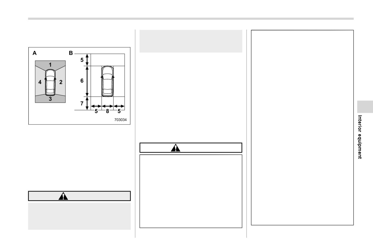
A
Camera to be used
such as spraying hot water on it
B
Range of displayed image
& Using the camera
in cold weather.
1
Front camera
Do not apply the water jet of a
2
Side camera (right-hand side)
CAUTION
high pressure washer to the cam-
3
Rear camera
era or the surrounding area when
4
Side camera (left-hand side)
Obey the following instructions to
5
Approx. 6 ft (2 m) from the vehicle
cleaning the vehicle. The force of
prevent a system malfunction.
6
Vehicle overall length
the water pressure can dislodge
. Do not apply any strong impact to
7
Approx. 8 ft (2.5 m) from the vehicle
the camera. Also, water may
the camera such as by hitting it
enter inside the camera and
8
Vehicle overall width
with an object. Striking the cam-
cause a malfunction.
era can change the mounting
WARNING
If the camera is exposed to any
angle.
impact, it can lead to a malfunc-
. The camera unit is a waterproof
The range that can be viewed with
tion. Have the camera inspected
structure. Do not attempt to re-
the camera is limited. Always make
by your SUBARU dealer as soon
sure that you check your surround-
move, disassemble or modify the
as possible.
unit.
ings directly when the vehicle is in
- CONTINUED -
328 Rear view camera
. Do not use a steam cleaner under
6-17. Rear view camera
and mirrors, and move backward
any circumstances. Some types
at a slow speed. Moving back-
of steam cleaners inject hot
ward only by checking the rear
steam.
view image from the camera
. The camera surface may be da-
could cause an accident.
maged by a flying stone.
Do not disassemble or modify the
camera, switch or wiring. If
smoke comes out or you smell a
NOTE
strange odor, stop using the rear
If the camera lens is covered in dirt, the
view camera immediately. Con-
system will not be able to produce a
tact your SUBARU dealer for an
sharp image. If there is foreign material
inspection. Continued use may
on the camera, such as water drops,
result in accident, fire or electric
snow or mud, clean it with water and
shock.
wipe away any moisture with a soft
cloth. If the camera is heavily soiled,
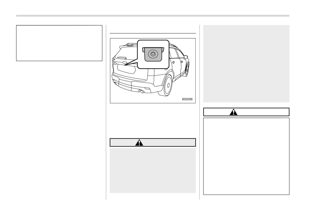
A rear view camera is attached to the rear
wash it using a neutral detergent.
gate. When the ignition switch is in the
CAUTION
“ON” position and the select lever is set to
“R”, the rear view camera automatically
When washing your vehicle with
displays the rear view image behind the
a high-pressure washer, do not
vehicle on the center information display.
allow water to touch the camera
directly. Entry of water in the
WARNING
camera lens may result in con-
densation, malfunction, fire or
. Since the rear view camera uses a
electric shock.
wide-angle lens, the image on the
Since the camera is a precision
monitor is different from the
device, do not subject it to strong
actual view in terms of distance.
impacts. Otherwise, malfunction,
. Since the range of the image on
fire or electric shock may occur.
the monitor is limited, always
If mud or snow sticks to or is
check the rear view and the
frozen on the camera, you must
surrounding area with your eyes
be very careful when removing it.
Rear view camera
329
Otherwise, damage to the camera
neutral detergent to remove the wax.
1. Set the ignition switch to “ON”.
may cause a fire or electric
The camera lens has a hard coating
2. Set the select lever to “R”.
shock. Pour water or lukewarm
to help prevent scratches. However,
water over the camera to remove
when washing the vehicle or clean-
NOTE
mud and ice, and wipe it with a
ing the camera lens, be careful not to
The image of the rear view camera is
soft, dry cloth.
scratch the camera lens. Do not use
a washing brush directly on the
horizontally reversed as is the case
Do not put a flame close to the
with the vehicle inside mirror or the
camera lens. The image quality of
camera or wiring. Otherwise, da-
outside mirror.
the rear view camera may deterio-
mage or fire may occur.
When “Rear Camera Delay Control”
rate.
When replacing the fuse, be sure
is on, the rear view image will be
Strong light shined on the camera
to use a fuse with the specified
displayed on the center information
lens may develop vertical lines
rating. Use of a fuse with a
display for a certain period of time
around the light source. This is not
different rating may result in a
after the select lever is shifted to a
a malfunction.
malfunction.
position other than the “P” position
Under the fluorescent light, the dis-
from “R”. To turn the function on and
If you use the rear view camera
play may flicker. However, this is not
off, refer to
“General settings”
for a long time while the engine is
a malfunction.
not operated, the battery may
The image of the rear view camera
FP210.
become completely discharged.
may be slightly different from the
It may be difficult to see the image of
the rear view camera in the following
actual color of the objects.
If there is a malfunction on the center
cases. This is not a malfunction of
NOTE
the camera.
information display, refer to “Mal-
. Do not wipe the camera with alcohol,
functions of the center information
- The vehicle is in a dark place (at
benzine or paint thinner. Otherwise,
display” FP467.
night, in a tunnel, etc.).
discoloration may occur. To remove
- The vehicle is in an extremely hot
contamination, wipe the camera with
or cold place.
& How to use the rear view
a cloth moistened with a diluted
- An object (such as raindrops,
camera
neutral detergent. Then wipe it with
snow, dirt, etc.) that disturbs the
a soft, dry cloth.
When the select lever is set to “R”, the rear
view of the rear view camera
. When waxing the vehicle, be careful
view camera automatically displays the
sticks to the lens of the camera.
not to apply the wax to the camera. If
rear view image from the vehicle. When
- Strong light is shining directly on
it comes in contact with the camera,
the lever is set to other positions, the
the camera lens (occasionally,
moisten a clean cloth with a diluted
image before setting to “R” is displayed.
- CONTINUED -
330 Rear view camera
there are vertical lines on the
Also, the image from the rear view camera
screen).
looks shorter than the actual distance.
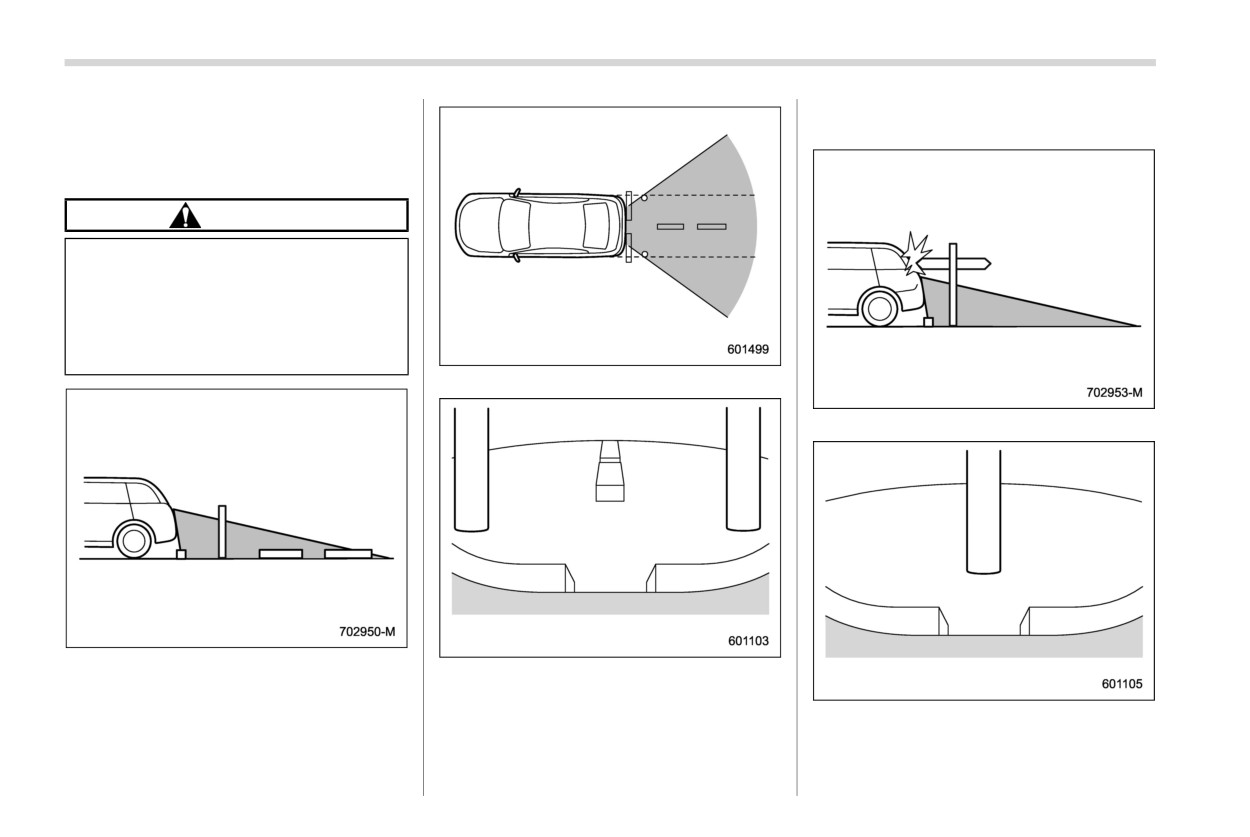
& Viewing range on the screen
CAUTION
The range that can be viewed with
the rear view camera is limited.
Always be sure to check with your
eyes when moving backward and
proceed slowly. Otherwise, it may
cause an accident or injury.
Range of view
Range of view
Range of view
Image from camera
The area from the rear end of the bumper
Image from camera
can be viewed. Areas at both ends of the
bumper and areas just under the bumper
The area above the camera cannot be
cannot be viewed.
viewed. If there is an object that has a wide
Rear view camera
331
projection on its upper part such as a sign
Otherwise, it may cause an acci-
pole behind the vehicle, the projection
dent or injury.
cannot be seen on the screen.
. The actual position may be differ-
ent from the indication of the help
& Help lines
lines.
The help lines are a guide to help you
. Differences may occur due to the
realize the actual distance from the screen
number of passengers or the
image.
loaded cargo.
NOTE
. When the vehicle is on a slope or
inclined against the road, the
If you shift to the
“R” range within
indication is different from the
several seconds after turning on the
actual position.
ignition switch, the warning message
Help lines
may not be displayed. Wait for several
1
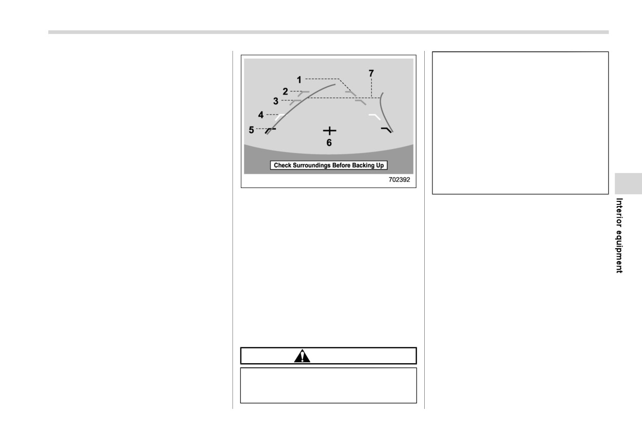
Vehicle width line (oblique vertical line)
seconds after turning on the ignition
2
Approx. 10 ft (3 m) from the bumper
NOTE
switch before shifting to the “R” range.
(green horizontal line)
When “Steering Angle Lines” is off, the
Then, the
warning
message
will
be
3
Approx. 6 ft (2 m) from the bumper (green
dynamic guidelines will be disappear
displayed.
horizontal line)
on the center information display. To
4
Approx.
3 ft
(1
m) from the bumper
turn the dynamic guidelines on and off,
(yellow horizontal line)
refer to “General settings” FP210.
5
Approx. 1.5 ft (0.5 m) from the bumper
(red horizontal line)
! Difference between screen image
6
Vehicle centerline
7
Dynamic guidelines
and actual road
The distance markers show the distance
When the select lever is set to “R”, the
for a level road when the vehicle is not
monitor screen displays the help lines
loaded. It may be different from the actual
together with the rear view image.
distance depending on the loading condi-
tions or road conditions.
CAUTION
. When moving backward, always
check the back with your eyes
without relying on the help lines.
- CONTINUED -
332 Rear view camera
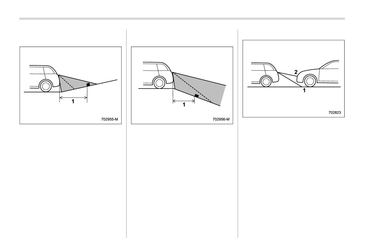
! When there is an upward slope at
! When there is a downward slope
! Feature of distance marker
the back
at the back
1
3 ft (1 m) line
1
3 ft (1 m)
1
3 ft (1 m)
2
10 ft (3 m) line
The distance on the screen looks farther
The distance on the screen looks nearer
The distance marker shows the distance
than the actual distance.
than the actual distance.
on the road. If there is a car or another
object close behind, distance cannot be
NOTE
correctly displayed.
When cargo is loaded, the rear view
distance on the screen looks farther
than the actual distance as in an
upward slope.
Starting and operating
Entering the vehicle following remote engine
7-1. Fuel
337
start shutdown
354
Fuel requirements
337
Pre-heating or pre-cooling the interior of
Fuel filler lid and cap
338
the vehicle
354
7-2. State emission testing (U.S. only)
342
Remote transmitter program (Remote engine
7-3. Preparing to drive
343
starter transceiver)
354
7-4. Starting and stopping the engine (models
System maintenance
355
without push-button start system)
344
Certification for remote engine starter
356
Starting engine
344
7-7. Continuously variable transmission
357
Stopping the engine
345
Continuously variable transmission features
357
Steering lock
345
Select lever
358
7-5. Starting and stopping engine (models
Selection of manual mode
359
with push-button start system)
346
Shift lock function
361
Safety precautions
346
Driving tips
362
Operating range for push-button start system
346
7
7-8. Power steering
362
Starting engine
346
Power steering warning light
362
Stopping engine
348
Power steering system features
362
When access key fob does not operate
7-9. Braking
363
properly
348
Braking tips
363
Steering lock
349
Brake system
364
7-6. Remote engine start system (dealer
Disc brake pad wear warning indicators
365
option)
349
7-10. ABS (Anti-lock Brake System)
365
Remote engine starter transceiver (fob)
350
ABS self-check
366
Alternate operation method for models with
ABS warning light
366
“keyless access with push-button start
system”
353
7-11. Electronic Brake Force Distribution (EBD)
Entering the vehicle while it is running via
system
366
remote start (models without “keyless access
If EBD system malfunctions
366
with push-button start system”)
353
7-12. Vehicle Dynamics Control system
367
Entering the vehicle while it is running via
Vehicle Dynamics Control system monitor
368
remote start (models with “keyless access
To turn on/off the Vehicle Dynamics Control
with push-button start system”)
354
system
368
Starting and operating
7-13. X-MODE
369
Reverse Automatic Braking (RAB) system
overview
392
To activate/deactivate X-MODE
370
Hill descent control function
372
Operating conditions
394
Sonar Audible Alarm function
397
7-14. Tire pressure monitoring system (TPMS)
Automatic Braking function operation
399
(U.S.-spec. models)
373
Canceling the Reverse Automatic Braking
7-15. Parking your vehicle
374
(RAB) system operation
400
Electronic parking brake
374
Reverse Automatic Braking (RAB) system
Parking tips
379
ON/OFF setting
401
7-16. Hill start assist system
380
RAB warning indicator
401
7-17. BSD/RCTA (if equipped)
382
Handling of the sonar sensors
402
System features
382
7-19. Driver Monitoring System (if equipped)
402
System operation
385
User recognition function
406
BSD/RCTA approach indicator light/warning
Inattentive/drowsy driving warning
408
buzzer
386
Driver Monitoring System indicator/warning
409
BSD/RCTA OFF indicator
388
Using the Driver Monitoring System
410
BSD/RCTA warning indicator
388
Registering and deleting a user
412
To turn on/off the BSD/RCTA
389
Registering and deleting driver position
Certification for the BSD/RCTA
389
personalization
412
Handling of radar sensors
390
Driver Monitoring System ON/OFF settings
412
7-18. Reverse Automatic Braking (RAB) system
How to get the source code using the Open
(if equipped)
391
Source
413
Fuel
337
which can damage the engine. Do not be
! MMT
7-1. Fuel
concerned if your vehicle sometimes
Some gasoline contains an octane-enhan-
knocks lightly when you drive up a hill or
cing additive called MMT
(Methylcyclo-
CAUTION
when you accelerate. Contact your
pentadienyl Manganese Tricarbonyl). If
SUBARU dealer if you use a fuel with the
you use such fuels, your emission control
. Use of a fuel which is low in
specified octane rating and your vehicle
system performance may deteriorate and
quality or use of an inappropriate
knocks heavily or persistently.
the CHECK ENGINE warning light/Mal-
fuel additive may cause damage
! RON
function indicator light may turn on. If this
to the engine and/or fuel system.
happens, return to your authorized
. Some gas stations, particularly
This octane rating is the Research Octane
SUBARU dealer for service. If it is deter-
Number.
those in high altitude areas, offer
mined that the condition is caused by the
fuels posted as regular octane
! AKI
type of fuel used, repairs may not be
gasoline with an octane rating
covered by your warranty.
This octane rating is the average of the
below 87 AKI (90 RON). Use of
Research Octane and Motor Octane num-
! Gasoline for cleaner air
those fuels is not recommended.
bers and is commonly referred to as the
Your use of gasoline with detergent ad-
Anti Knock Index (AKI).
ditives will help prevent deposits from
& Fuel requirements
! Unleaded gasoline
forming in your engine and fuel system.
This helps keep your engine in tune and
The engine is designed to operate using
The neck of the fuel filler pipe is designed
your emission control system working
unleaded gasoline with an octane rating
to accept only an unleaded gasoline filler
properly, and is a way of doing your part
of 87 AKI (90 RON) or higher.
nozzle. Under no circumstances should
for cleaner air. If you continuously use a
leaded gasoline be used because it will
NOTE
high-quality fuel with the proper detergent
damage the emission control system and
and other additives, you should never
When towing a trailer, SUBARU recom-
may impair driveability and fuel economy.
need to add any fuel system cleaning
mends using unleaded gasoline with an
! Reformulated gasoline
octane rating of 91 AKI (95 RON) or
agents to your fuel tank.
SUBARU supports the use of reformulated
higher to reduce the risk of engine
Many gasolines are now blended with
gasoline when available. Reformulated
overheat.
materials called oxygenates. Use of these
gasoline has been blended to burn more
fuels can also help keep the air cleaner.
! Fuel octane rating
cleanly and reduce vehicle emissions.
Oxygenated blend fuels, such as ethanol
Using a gasoline with a lower octane rating
(ethyl or grain alcohol) may be used in your
can cause persistent and heavy knocking,
vehicle, but should contain no more than
- CONTINUED -