Subaru Impreza WRX (2014 year). Instruction - part 11


  Index      Subaru     Subaru Impreza WRX - instruction 2014 year in english


Search            


Content   ..  9  10  11  12   ..


Subaru Impreza WRX (2014 year). Instruction - part 11


3-46

Instruments and controls/Mirrors

!

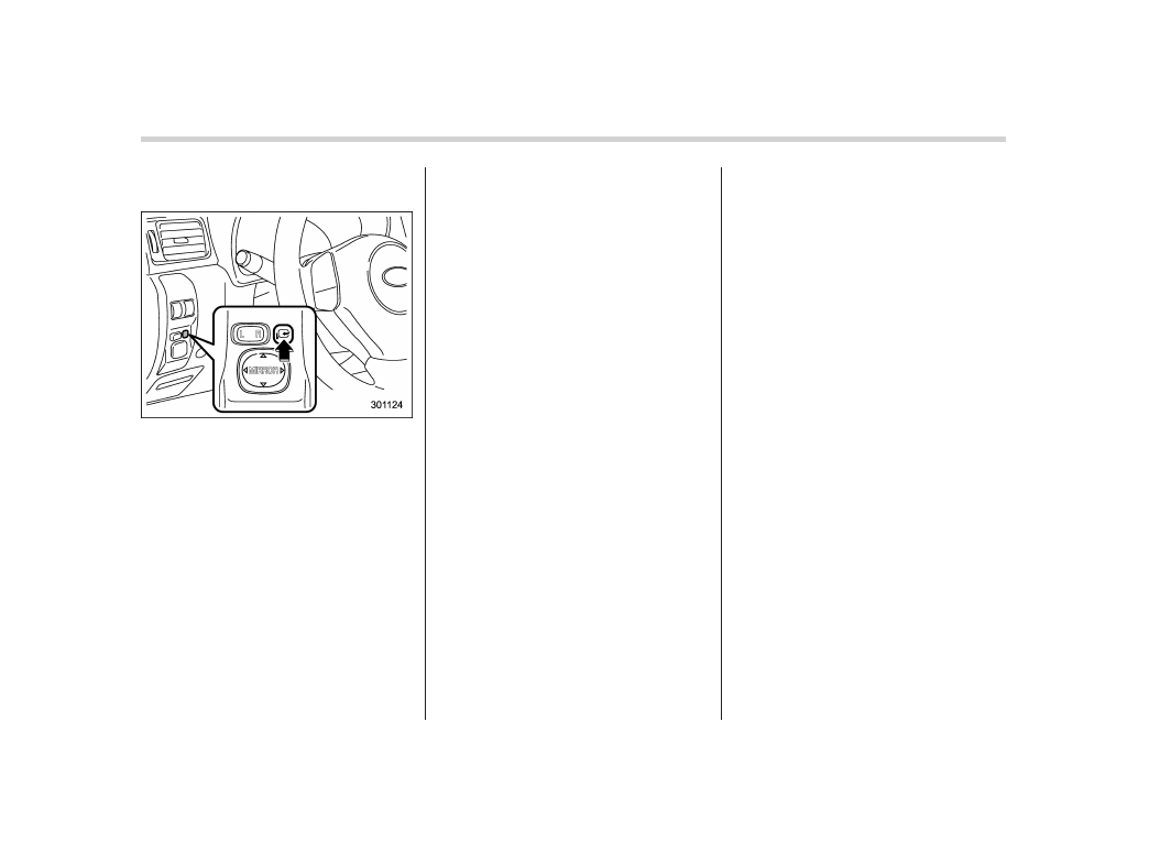
Power folding mirror switch (if
equipped)

The power folding mirror switch operates
only when the ignition switch is in the “ON”
or “Acc” position.
To fold the outside mirrors, push the power
folding mirror switch. To unfold the mirrors,
push the switch again.

NOTE

. If the outside mirrors have been
operated (folded or unfolded) manually,
when you turn the ignition switch from
the “LOCK/OFF” position to the “Acc”
or “ON” position, the outside mirrors
may be adjusted automatically depend-
ing on the status of the power folding
mirror switch.
. If the outside mirrors have been

manually folded slightly forward of the
regularly unfolded position, when you
turn the ignition switch from the
“LOCK/OFF” position to the “Acc” or
“ON” position, the outside mirrors may
automatically fold further forward de-
pending on the status of the power
folding mirror switch. When this hap-
pens, press the power folding mirror
switch. By doing so, the outside mir-
rors which have been folded to the
furthest forward position will extend to
the regularly unfolded position and
then fold rearward in the usual way. In
order to unfold the outside mirrors,
press the switch again.
. When you unfold the outside mirrors
manually, the mirrors may become
wobbly. Be sure to unfold the mirrors
by switch operation. If the outside
mirrors are still wobbly, fold the mirrors
again and then unfold them by switch
operation.
. When the temperature is low, the
outside mirrors may stop during switch
operation. If that occurs, push the
switch again. When the outside mirrors
do not work by switch operation, move
them several times manually. This
makes it possible to operate them by
switch operation.
. When you operate the power folding
mirror switch continuously, it may not

work. This is not a malfunction. Oper-
ate the switch again after waiting for a
short period of time.

Defogger and deicer

1)

Rear window defogger

2)

Outside mirror defogger (if equipped)

3)

Windshield wiper deicer (if equipped)

The vehicle is equipped with a rear

window defogger. Some models are also
equipped with an outside mirror defogger
and/or windshield wiper deicer. The de-
fogger and deicer system is activated only
when the ignition switch is in the “ON”
position.

Manual climate control system

Automatic climate control system

To activate the defogger and deicer
system, push the control switch that is
located on the climate control panel. The
rear window defogger, outside mirror
defogger and windshield wiper deicer are
activated simultaneously. The indicator
light on the control switch illuminates while
the defogger and deicer system is acti-
vated.

To turn them off, push the control switch
again. They also turn off when the ignition
switch is turned to the “Acc” or “LOCK”
position.

The defogger and deicer system will
automatically shut off after approximately
15 minutes. If the rear window and the
outside mirrors have been cleared and the

Instruments and controls/Defogger and deicer

3-47

– CONTINUED –

3-48

Instruments and controls/Tilt/telescopic steering wheel

windshield wiper blades have been deiced
completely before that time, push the
control switch to turn them off. If defrost-
ing, defogging or deicing is not complete,
you have to push the control switch to turn
them on again.

For models with the automatic climate
control system, it is possible to have the
defogger and deicer system for the con-
tinuous operation mode set by a SUBARU
dealer. Consult your SUBARU dealer for
details.

If the battery voltage drops below the
permissible level, continuous operation of
the defogger and deicer system is can-
celed and the system stops operating.

CAUTION

. To prevent the battery from being

discharged, do not operate the
defogger and deicer system con-
tinuously for any longer than
necessary.

. Do not use sharp instruments or

window cleaner containing abra-
sives to clean the inner surface
of the rear window. They may
damage the conductors printed
on the window.

NOTE

. Turn on the defogger and deicer
system if the wipers are frozen to the
windshield.
. If the windshield is covered with
snow, remove the snow so that the
windshield wiper deicer works effec-
tively.
. While the defogger and deicer sys-
tem is in the continuous operation
mode, if the vehicle speed remains at
9 mph (15 km/h) or less for 15 minutes,
the windshield wiper deicer automati-
cally stops operating, though the rear
window defogger and outside mirror
defogger maintain continuous opera-
tion in this condition.

Tilt/telescopic steering wheel

WARNING

. Do not adjust the steering wheel

tilt/telescopic position while driv-
ing. This may cause loss of
vehicle control and result in
personal injury.

. If the lever cannot be raised to

the fixed position, adjust the
steering wheel again. It is dan-
gerous to drive without locking
the steering wheel. This may
cause loss of vehicle control
and result in personal injury.

1)

Tilt adjustment

2)

Telescopic adjustment

1. Adjust the seat position. Refer to
“Front seats” F1-2.
2. Pull the tilt/telescopic lock lever down.
3. Move the steering wheel to the desired
level.
4. Pull the lever up to lock the steering
wheel in place.
5. Make sure that the steering wheel is
securely locked by moving it up and down,
and forward and backward.

Horn

To sound the horn, push the horn pad.

Instruments and controls/Horn

3-49

— — — — — — — — — — — — — — — — — — — — — — — — — — — — — — — — — — — — — — — —

— — — — — — — — — — — — — — — — — — — — — — — — — — — — — — — — — — — — — — — —

— — — — — — — — — — — — — — — — — — — — — — — — — — — — — — — — — — — — — — — —

— — — — — — — — — — — — — — — — — — — — — — — — — — — — — — — — — — — — — — — —

— — — — — — — — — — — — — — — — — — — — — — — — — — — — — — — — — — — — — — — —

— — — — — — — — — — — — — — — — — — — — — — — — — — — — — — — — — — — — — — — —

— — — — — — — — — — — — — — — — — — — — — — — — — — — — — — — — — — — — — — — —

— — — — — — — — — — — — — — — — — — — — — — — — — — — — — — — — — — — — — — — —

— — — — — — — — — — — — — — — — — — — — — — — — — — — — — — — — — — — — — — — —

— — — — — — — — — — — — — — — — — — — — — — — — — — — — — — — — — — — — — — — —

— — — — — — — — — — — — — — — — — — — — — — — — — — — — — — — — — — — — — — — —

— — — — — — — — — — — — — — — — — — — — — — — — — — — — — — — — — — — — — — — —

— — — — — — — — — — — — — — — — — — — — — — — — — — — — — — — — — — — — — — — —

Ventilator..............................................................

4-2

Airflow selection .................................................

4-2

Center and side ventilators ..................................

4-3

Manual climate control system (if

equipped) ..........................................................

4-3

Control panel ......................................................

4-3

Heater operation .................................................

4-5

Air conditioner operation .....................................

4-7

Automatic climate control system (if

equipped) ..........................................................

4-8

Control panel ......................................................

4-8

To use as full-automatic climate control

system..............................................................

4-8

To use as semi-automatic climate control

system..............................................................

4-8

Fan speed control dial.........................................

4-9

Temperature control dial......................................

4-9

Airflow control dial ..............................................

4-9

Air inlet selection button ....................................

4-10

Air conditioner button ........................................

4-11

Temperature sensors .........................................

4-11

Operating tips for heater and air

conditioner ......................................................

4-12

Cleaning ventilation grille...................................

4-12

Efficient cooling after parking in direct

sunlight ...........................................................

4-12

Lubrication oil circulation in the refrigerant

circuit..............................................................

4-12

Checking air conditioning system before summer

season ............................................................

4-12

Cooling and dehumidifying in high humidity and

low temperature weather conditions .................

4-12

Air conditioner compressor shut-off when engine

is heavily loaded..............................................

4-13

Refrigerant for your climate control system ........

4-13

Air filtration system ...........................................

4-13

Replacing an air filter.........................................

4-13

Climate control

4

4-2

Climate control/Ventilator

Ventilator

&

Airflow selection

&

Center and side ventilators

!

Center ventilators

Move the tab to adjust the flow direction.

!

Side ventilators

1)

Open

2)

Close

3)

Thumb-wheel

Move the tab to adjust the flow direction.
To open or close the ventilator, turn the
thumb-wheel up or down.

Manual climate control sys-
tem (if equipped)

&

Control panel

1)

Temperature control dial

2)

Fan speed control dial

3)

Airflow control dial

4)

Control switch of the defogger and deicer
system (Refer to “Defogger and deicer”
F3-47.)

5)

Air conditioner button

6)

Air inlet selection button

!

Temperature control dial

This dial regulates the temperature of
airflow from the air outlets over a range
from the blue side (cool) to red side
(warm).

Climate control/Manual climate control system

4-3

– CONTINUED –

4-4

Climate control/Manual climate control system

!

Fan speed control dial

The fan operates only when the ignition
switch is turned to the “ON” position. The
fan speed control dial is used to select
four fan speeds.

!

Airflow control dial

Each dial position activates the following
air outlets.

(Ventilation): Instrument panel outlets

(Bi-level): Instrument panel outlets and

foot outlets

(Heat): Foot outlets, both side outlets of

the instrument panel and some through
windshield defroster outlets (A small
amount of air flows to the windshield and
both side windows to prevent fogging.)

(Heat-def): Windshield defroster out-

lets, foot outlets and both side outlets of
the instrument panel

: Windshield defroster outlets and both

side outlets of the instrument panel

For details, refer to “Airflow selection” F4-
2.

NOTE

When the dial is placed in the “

” or

“ ” position, the air conditioner com-
pressor operates automatically regard-

less of the position of the air condi-
tioner button to defog the windshield
more quickly. However the indicator on
the air conditioner button will not
illuminate. At the same time, the air
inlet selection is automatically set to
“outside air” mode.
In this state, you cannot select “recir-
culation” mode by manually pressing
the air inlet selection button.
Also, you cannot stop the air condi-
tioner compressor by pressing the air
conditioner button.

!

Air conditioner button

The air conditioner operates only when
the engine is running.

Press the air conditioner button while the
fan is in operation to turn on the air

conditioner. The indicator light will illumi-
nate.

Press it again to turn off the air condi-
tioner.

!

Air inlet selection button

ON position (recirculation): Interior air is
recirculated inside the vehicle. Press the
air inlet selection button to the ON posi-
tion. The indicator light will illuminate.
Place the air inlet selection button to the
ON position for fast cooling with the air
conditioner or when driving on a dusty
road.

OFF position (outside air): Outside air is
drawn into the passenger compartment.
Press the air inlet selection button again to
the OFF position. The indicator light will
turn off.

Place the air inlet selection button to the
OFF position when the interior has cooled
to a comfortable temperature and the road
is no longer dusty.

WARNING

Continued operation with the air
inlet selection button in the ON
position may fog up the windows.
Switch to the OFF position as soon
as the outside dusty condition
clears.

&

Heater operation

NOTE

. When the “

” or “ ” position is

selected, the air conditioner compres-
sor automatically operates regardless
of the position of the air conditioner
button to defog the windshield more
quickly. At the same time, the air inlet
selection is automatically switched to
the OFF position (outside air). How-
ever, the air conditioner indicator light
does not illuminate at this time.
. When defrosting, defogging or heat-
ing, warm air is also emitted from the
right and left air outlets. To stop warm
airflow from these outlets, turn the
corresponding thumb wheel down.

!

Defrosting or defogging the wind-
shield

To direct warm air to the windshield and
front door windows:
1. Set the airflow control dial to the “

position.
2. Turn the temperature control dial all
the way to the right.
3. Set the fan speed control dial to the
highest speed.

!

Heating and defrosting

To direct warm air toward the floor and the
windshield:
1. Set the airflow control dial to the “ ”
position.
2. Set the temperature control dial to the
most comfortable level.
3. Set the fan speed control dial to the
desired speed.

Climate control/Manual climate control system

4-5

– CONTINUED –

4-6

Climate control/Manual climate control system

!

Heating

To direct warm air toward the floor:
1. Set the air inlet selection button to the
OFF position.
2. Set the airflow control dial to the “

position.
3. Set the temperature control dial to the
most comfortable level.
4. Set the fan speed control dial to the
desired speed.

!

Bi-level heating

This setting allows you to direct air of
different temperatures from the instrument
panel and foot outlets. The air from the
foot outlets is slightly warmer than from
the instrument panel outlets.
1. Set the air inlet selection button to the
OFF position.
2. Set the airflow control dial to the “

position.
3. Set the temperature control dial to the
desired temperature level.
4. Set the fan speed control dial to the
desired speed.

Setting the temperature control dial fully
turned to the red area or blue area
decreases the temperature difference
between the air from the instrument panel

outlets and the air from the foot outlets.

!

Ventilation

To force outside air through the instrument
panel outlets:
1. Set the air inlet selection button to the
OFF position.
2. Set the airflow control dial to the “ ”
position.
3. Set the temperature control dial all the
way left.
4. Set the fan speed control dial to the
desired speed.

When driving on a dusty road, set the air
inlet selection button to the “ON” position.

WARNING

Continued operation with the air

inlet selection button in the ON
position may fog up the windows.
Switch to the OFF position as soon
as the outside dusty condition
clears.

&

Air conditioner operation

!

Cooling or dehumidifying

1)

ON position

For cooling and dehumidification of the
passenger compartment, performing the
following steps will allow air to flow
through the instrument panel outlets:
1. Set the air inlet selection button to the
OFF position.
2. Set the airflow control dial to the “ ”
position.

3. Set the air conditioner button to the
“ON” position.
4. Set the temperature control dial to the
blue side.
5. Set the fan speed control dial at the
highest speed.

!

Defrosting or defogging

To direct warm air to the windshield and
front door windows:
1. Set the airflow control dial to the “

position.
2. Set the temperature control dial to the
red side.
3. Set the fan speed control dial at the
highest speed.

The air conditioner compressor automati-
cally operates when the airflow control dial

set in the “

” or “ ” position to provide

better defogging performance.

Climate control/Manual climate control system

4-7

4-8

Climate control/Automatic climate control system

Automatic climate control
system (if equipped)

Although this climate control system can
be used as a full-automatic climate control
system, it can also, if desired, be used as
a semi-automatic climate control system.
When it is used as a full-automatic climate
control system, the outlet air temperature,
fan speed, airflow distribution, air inlet
control, and air conditioner compressor
operation are all automatically controlled
to maintain a constant, comfortable tem-
perature inside the vehicle.

NOTE

. Operate the automatic climate con-
trol system when the engine is running.
. When the engine coolant is cold, the
blower does not run.
. In the “AUTO” mode, when the air
temperature in the passenger compart-
ment is sufficiently cool, the air condi-
tioner compressor does not operate.
For efficient defogging or dehumidify-
ing in cold weather, press the “A/C”
button to operate the air conditioner
compressor.

&

Control panel

1)

Temperature control dial

2)

Fan speed control dial

3)

Airflow control dial

4)

Control switch of the defogger and deicer
system (Refer to “Defogger and deicer”
F3-47.)

5)

Air inlet selection button

6)

Air conditioner button

&

To use as full-automatic cli-
mate control system

Place the temperature control dial in the
position for your desired temperature, then
set the other dials and buttons as de-
scribed in the following. The system’s
functions will then switch to AUTO mode
and be controlled automatically.
. Airflow control dial: AUTO position
. Fan speed control dial: AUTO position

&

To use as semi-automatic
climate control system

Each function can be individually set to
AUTO mode independently of the others.
Any function set to AUTO mode is con-
trolled automatically. Any function not set
to AUTO mode can be manually adjusted
as desired.
The temperature can be set within a range
of 65 to 858F (20 to 308C).

&

Fan speed control dial

The fan operates only with the ignition
switch in the ON position. The fan speed
control dial is used to select the AUTO
(automatic control) mode or to select the
desired fan speed. The dial’s positions
and their functions are as follows.
OFF: The fan does not operate. When the
AUTO mode is operating, the setting of air
inlet is fixed in the “OFF” position (outside
air). When the AUTO mode is not operat-
ing, the setting will remain in the condition
set just before the air conditioner turned
off.
AUTO: The fan speed is adjusted auto-
matically in accordance with the air
temperature inside and outside the pas-
senger compartment, the intensity of sun-
light, and other factors. SUBARU recom-

mends using the AUTO position.
Other positions: The fan speed can be
adjusted in 7 steps.

NOTE

With the fan speed control dial in the
AUTO position and the airflow control
dial in the “

”, “

”, or “ ” position,

the fan does not operate during engine
warm-up until the engine coolant tem-
perature exceeds approximately 1228F
(508C).

&

Temperature control dial

This dial is used to set the desired interior
temperature. With the dial set to your
desired temperature, the system automa-
tically adjusts the temperature of air
supplied from the outlets such that the

desired temperature is achieved and
maintained.
If the dial is turned fully counterclockwise,
the system gives maximum cooling per-
formance. If the dial is turned fully clock-
wise, the system gives maximum heating
performance.

&

Airflow control dial

Each dial position activates the following
air outlets.
AUTO: The airflow control is adjusted
automatically in accordance with the air
temperature inside and outside the pas-
senger compartment, the intensity of sun-
light, and other factors. SUBARU recom-
mends using the AUTO position.

(Ventilation): Instrument panel outlets

Climate control/Automatic climate control system

4-9

– CONTINUED –

4-10

Climate control/Automatic climate control system

(Bi-level): Instrument panel outlets and

foot outlets

(Heat): Foot outlets, both side outlets of

the instrument panel and some through
windshield defroster outlets (A small
amount of air flows to the windshield and
both side windows to prevent fogging.)

(Heat-def): Windshield defroster out-

lets, foot outlets and both side outlets of
the instrument panel

: Windshield defroster outlets and both

side outlets of the instrument panel

For details, refer to “Airflow selection” F4-
2.

NOTE

When the dial is placed in the “

” or

“ ” position, the air inlet selection is
automatically set to “outside air”
mode.

&

Air inlet selection button

ON position (recirculation): Interior air is
recirculated inside the vehicle. Press the
air inlet selection button to the ON position
for fast cooling with the air conditioner or
when driving on a dusty road. The
indicator light will illuminate.
OFF position (outside air): Outside air is
drawn into the passenger compartment.
Press the air inlet selection button to the
OFF position when the interior has cooled
to a comfortable temperature and the road
is no longer dusty. The indicator light will
turn off.
AUTO: Turn the fan speed control dial and
airflow control dial to the AUTO position.
The air inlet control is then adjusted
automatically in accordance with the air
temperature inside and outside the pas-

senger compartment, the intensity of sun-
light, and other factors. Pressing the air
inlet selection button cancels the “AUTO”
mode. To return to “AUTO” mode, turn the
fan speed control dial or airflow control
dial to a position other than the AUTO
position. Then turn to “AUTO” mode.
SUBARU recommends using the AUTO
position.

WARNING

Continued operation in the ON posi-
tion may fog up the windows. Switch
to the OFF position as soon as the
outside dusty condition clears.

NOTE

When the battery is disconnected or
when the battery voltage is low, the
indicator light will blink but this is not a
malfunction. However, an electrical
system malfunction may occur if the
indicator light is blinking when the
engine is started. Have your vehicle
inspected by a SUBARU dealer.

&

Air conditioner button

The button positions and their functions
are as follows.
ON: The air conditioner operates while the
fan is running.
Press the button to select this position.
The indicator light will illuminate.
OFF: The air conditioner does not oper-
ate.
Press the button again to select this
position. The indicator light will turn off.
AUTO: Turn the fan speed control dial and
airflow control dial to the AUTO position.
The air conditioner compressor operation
is then adjusted automatically in accor-
dance with the air temperature inside and
outside the passenger compartment, the
intensity of sunlight, and other factors.

Pressing the button cancels the “AUTO”
mode. To return to “AUTO” mode, turn the
fan speed control dial or airflow control
dial to a position other than the AUTO
position. Then turn to “AUTO” mode.
SUBARU recommends using the AUTO
position.

NOTE

For efficient defogging or dehumidify-
ing in cold weather, turn on the air
conditioner. However, if the ambient
temperature decreases to approxi-
mately 328F (08C), the air conditioner
and dehumidification system may not
work properly.

&

Temperature sensors

1)

Interior air temperature sensor

2)

Solar sensor

The automatic climate control system
employs several sensors. These sensors
are delicate. If they are not treated

Climate control/Automatic climate control system

4-11

– CONTINUED –


Content   ..  9  10  11  12   ..