Subaru Legacy IV (2008 year). Manual - part 942
 

  Index      Subaru     Subaru Legacy IV - service repair manual 2008 year


Search            


Content   ..  940  941  942  943   ..


Subaru Legacy IV (2008 year). Manual - part 942


VDC(diag)-83

Diagnostic Procedure with Diagnostic Trouble Code (DTC)

VEHICLE DYNAMICS CONTROL (VDC) (DIAGNOSTICS)

AP:DTC C0071 STEERING ANGLE SENSOR MALFUNCTION

DTC DETECTING CONDITION:
Defective steering angle sensor
TROUBLE SYMPTOM:
• ABS does not operate.
• VDC does not operate.

NOTE:
• Warning light does not illuminate though problem is detected.
• The ABS and VDC operate normally if voltage returns.
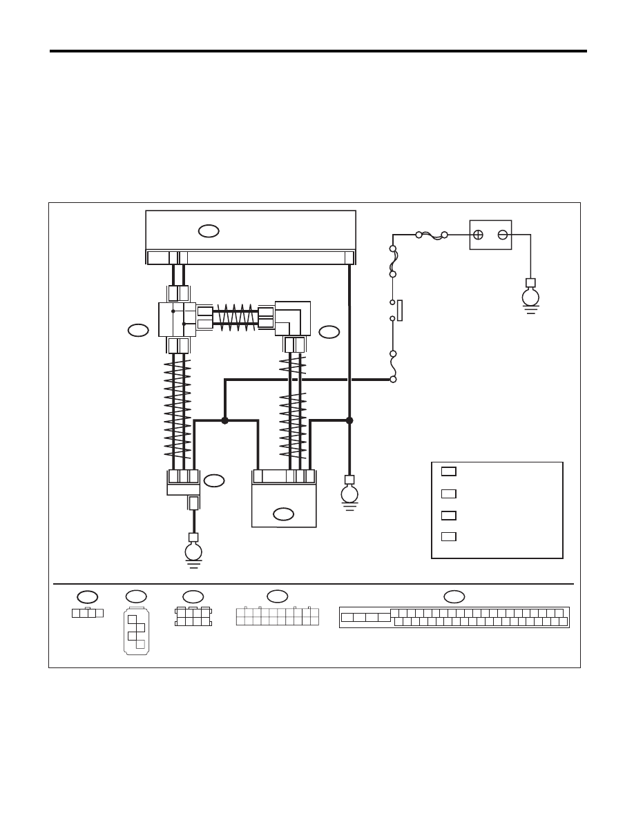
WIRING DIAGRAM:

VDC00473

1 2 3 4

B310

VDCCM & H/U

25

10

35

B231

B230

2

4

1

1

4

2

3

3

STEERING
ANGLE
SENSOR

YAW RATE & 
LATERAL G 
SENSOR

E

E

B231

SBF-6

MAIN SBF

No.33

E

IGNITION
SWITCH

BATTERY

B310

4 5 6 7 8 9

26 27 28 29 30

2 3

1

31 32 33 34 35 36

10 11

14 15 16 17 18 19

37 38 39 40

12 13

41 42 43 44 45 46

20 21

23

24

22

25

B230

1

2

3

4

TWISTED PAIR LINE

TWISTED PAIR LINE

B365

B170

CAN
JOINT
CONNECTOR

4

*

3

*

4

3

*

*

2

1 :

:

*

*

CAN
JOINT
CONNECTOR

TERMINAL No. OPTIONAL 
ARRANGEMENT AMONG 
1, 2, 3,11,12 AND 13

TERMINAL No. OPTIONAL 
ARRANGEMENT AMONG
8, 9, 10, 18, 19 AND 20 

4

3 :

:

*

*

TERMINAL No. OPTIONAL 
ARRANGEMENT AMONG 
1, 2, 5  AND 6 

TERMINAL No. OPTIONAL 
ARRANGEMENT AMONG
3, 4, 7 AND 8 

2

1

* *

2

1

* *

2

1

*

*

TWISTED
PAIR LINE

B170

3 4

5 6

1 2

7 8

1 2 3 4 5 6 7 8 9 10

11 12 13 14 15 16 17 18 19 20

B365

VDC(diag)-84

Diagnostic Procedure with Diagnostic Trouble Code (DTC)

VEHICLE DYNAMICS CONTROL (VDC) (DIAGNOSTICS)

Step

Check

Yes

No

1

CHECK POWER SUPPLY FOR STEERING 
ANGLE SENSOR.
1) Turn the ignition switch to OFF.
2) Disconnect the connector from steering 
angle sensor.
3) Turn the ignition switch to ON.
4) Measure the voltage between the steering 
angle sensor and chassis ground.

Connector & terminal

(B231) No. 4 (+) — Chassis ground (–):

Is the voltage 10 — 15 V?

Go to step 2.

Repair the power 
supply circuit of 
steering angle sen-
sor.

2

CHECK GROUND CIRCUIT OF STEERING 
ANGLE SENSOR.
Measure the resistance between steering angle 
sensor and chassis ground.

Connector & terminal

(B231) No. 3 — Chassis ground:

Is the resistance less than 0.5 

:? Go to step 3.

Repair ground cir-
cuit in the steering 
angle sensor.

3

CHECK STEERING ANGLE SENSOR.
1) Turn the ignition switch to OFF.
2) Connect all connectors.
3) Clear the memory. <Ref. to VDC(diag)-23, 
Clear Memory Mode.>
4) Perform the Inspection Mode. <Ref. to 
VDC(diag)-22, Inspection Mode.>
5) Read the DTC. 

Is the same DTC displayed?

Go to step 4.

Go to step 5.

4

CHECK VDCCM&H/U.
1) Turn the ignition switch to OFF.
2) Replace the steering angle sensor.
3) Clear the memory. <Ref. to VDC(diag)-23, 
Clear Memory Mode.>
4) Perform the Inspection Mode. <Ref. to 
VDC(diag)-22, Inspection Mode.>
5) Read the DTC. 

Is the same DTC displayed?

Replace the 
VDCCM only. 
<Ref. to VDC-10, 
REPLACEMENT, 
VDC Control Mod-
ule and Hydraulic 
Control Unit 
(VDCCM&H/U).>

Go to step 6.

5

CHECK OTHER DTC DETECTION.

Is any other DTC displayed?

Perform the diag-
nosis according to 
DTC. <Ref. to 
VDC(diag)-34, List 
of Diagnostic Trou-
ble Code (DTC).>

Temporary poor 
contact occurs.

6

CHECK OTHER DTC DETECTION.

Is any other DTC displayed?

Perform the diag-
nosis according to 
DTC. <Ref. to 
VDC(diag)-34, List 
of Diagnostic Trou-
ble Code (DTC).>

Original steering 
angle sensor mal-
function

VDC(diag)-85

Diagnostic Procedure with Diagnostic Trouble Code (DTC)

VEHICLE DYNAMICS CONTROL (VDC) (DIAGNOSTICS)

AQ:DTC C0072 ABNORMAL YAW RATE SENSOR OUTPUT

DTC DETECTING CONDITION:
Defective yaw rate sensor
TROUBLE SYMPTOM:
VDC does not operate.
WIRING DIAGRAM:

VDC00473

1 2 3 4

B310

VDCCM & H/U

25

10

35

B231

B230

2

4

1

1

4

2

3

3

STEERING
ANGLE
SENSOR

YAW RATE & 
LATERAL G 
SENSOR

E

E

B231

SBF-6

MAIN SBF

No.33

E

IGNITION
SWITCH

BATTERY

B310

4 5 6 7 8 9

26 27 28 29 30

2 3

1

31 32 33 34 35 36

10 11

14 15 16 17 18 19

37 38 39 40

12 13

41 42 43 44 45 46

20 21

23

24

22

25

B230

1

2

3

4

TWISTED PAIR LINE

TWISTED PAIR LINE

B365

B170

CAN
JOINT
CONNECTOR

4

*

3

*

4

3

*

*

2

1 :

:

*

*

CAN
JOINT
CONNECTOR

TERMINAL No. OPTIONAL 
ARRANGEMENT AMONG 
1, 2, 3,11,12 AND 13

TERMINAL No. OPTIONAL 
ARRANGEMENT AMONG
8, 9, 10, 18, 19 AND 20 

4

3 :

:

*

*

TERMINAL No. OPTIONAL 
ARRANGEMENT AMONG 
1, 2, 5  AND 6 

TERMINAL No. OPTIONAL 
ARRANGEMENT AMONG
3, 4, 7 AND 8 

2

1

* *

2

1

* *

2

1

*

*

TWISTED
PAIR LINE

B170

3 4

5 6

1 2

7 8

1 2 3 4 5 6 7 8 9 10

11 12 13 14 15 16 17 18 19 20

B365

VDC(diag)-86

Diagnostic Procedure with Diagnostic Trouble Code (DTC)

VEHICLE DYNAMICS CONTROL (VDC) (DIAGNOSTICS)

Step

Check

Yes

No

1

CHECK DRIVING PLACE.
Check if the vehicle ran the road with banks or 
sandy surface (which does not mean a dirt 
road).

Did the vehicle run the road 
with banks or sandy surface 
(which does not mean a dirt 
road)?

VDCCM&H/U may 
record DTC when 
the vehicle ran the 
road with banks or 
sandy surface 
(which does not 
mean a dirt road).

Go to step 2.

2

CHECK YAW RATE & LATERAL G SENSOR 
INSTALLATION.

Is the yaw rate & lateral G sen-
sor installation bolt tightened to 
7.5 N·m (0.76 kgf-m, 5.5 ft-lb)?

Go to step 3.

Tighten the yaw 
rate & lateral G 
sensor installation 
bolt.

3

CHECK OUTPUT OF YAW RATE & LATERAL 
G SENSOR WITH SUBARU SELECT MONI-
TOR.
1) Drive the vehicle on a flat road.
2) Park the vehicle straight.
3) Select {Current Data Display & Save} in the 
Subaru Select Monitor.
4) Read the yaw rate output displayed on dis-
play.

Is the reading indicated on 
monitor display –4 — 4 deg/s?

Go to step 4.

Replace the yaw 
rate & lateral G 
sensor.

4

CHECK OUTPUT OF STEERING ANGLE 
SENSOR WITH SUBARU SELECT MONI-
TOR.
1) Drive the vehicle on a flat road.
2) Park the vehicle straight.
3) Select {Current Data Display & Save} in the 
Subaru Select Monitor.
4) Read the steering angle sensor output dis-
played on display.

Is the reading indicated on 
monitor display –5 — 5°?

Go to step 5.

Perform the cen-
tering adjustment 
of steering wheel.

5

CHECK YAW RATE & LATERAL G SENSOR.
1) Turn the ignition switch to OFF.
2) Connect all connectors.
3) Clear the memory. <Ref. to VDC(diag)-23, 
Clear Memory Mode.>
4) Perform the Inspection Mode. <Ref. to 
VDC(diag)-22, Inspection Mode.>
5) Read the DTC. 

Is the same DTC displayed?

Go to step 6.

Go to step 7.

6

CHECK VDCCM&H/U.
1) Turn the ignition switch to OFF.
2) Replace the yaw rate & lateral G sensor.
3) Clear the memory. <Ref. to VDC(diag)-23, 
Clear Memory Mode.>
4) Perform the Inspection Mode. <Ref. to 
VDC(diag)-22, Inspection Mode.>
5) Read the DTC. 

Is the same DTC displayed?

Replace the 
VDCCM only. 
<Ref. to VDC-10, 
REPLACEMENT, 
VDC Control Mod-
ule and Hydraulic 
Control Unit 
(VDCCM&H/U).>

Go to step 8.

7

CHECK OTHER DTC DETECTION.

Is any other DTC displayed?

Perform the diag-
nosis according to 
DTC. <Ref. to 
VDC(diag)-34, List 
of Diagnostic Trou-
ble Code (DTC).>

Temporary poor 
contact occurs.

8

CHECK OTHER DTC DETECTION.

Is any other DTC displayed?

Perform the diag-
nosis according to 
DTC. <Ref. to 
VDC(diag)-34, List 
of Diagnostic Trou-
ble Code (DTC).>

Malfunction is 
found in original 
yaw rate & lateral 
G sensor.


Content   ..  940  941  942  943   ..