Subaru Legacy IV (2008 year). Manual - part 937
VDC(diag)-63
Diagnostic Procedure with Diagnostic Trouble Code (DTC)
VEHICLE DYNAMICS CONTROL (VDC) (DIAGNOSTICS)
AD:DTC C0051 VALVE RELAY
DTC DETECTING CONDITION:
Defective valve relay
TROUBLE SYMPTOM:
• ABS does not operate.
• EBD does not operate.
• VDC does not operate.
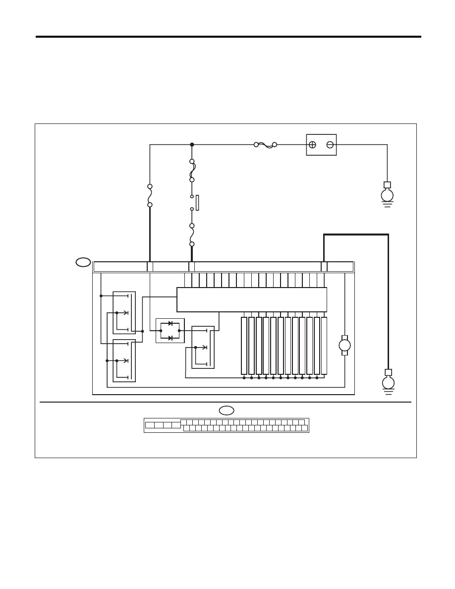
WIRING DIAGRAM:
B310
E
24
25
VDCCM & H/U
28
PUMP MOTOR
M
FL INLET
MAIN SBF
SBF-6
No.1
No.33
E
BATTERY
IGNITION
SWITCH
SOLENOID VALVE
FR INLET
RL INLET
RR INLET
FL OUTLET
FR OUTLET
RL OUTLET
RR OUTLET
PRIMARY CUT
SECONDARY CUT
PRIMARY SUCTION
MOTOR RELAY
VALVE RELAY
SECONDARY SUCTION
B310
4 5 6 7 8 9
26 27 28 29 30
2 3
1
31 32 33 34 35 36
10 11
14 15 16 17 18 19
37 38 39 40
12 13
41 42 43 44 45 46
20 21
23
24
22
25
VDC00466