Subaru Legacy IV (2008 year). Manual - part 892


  Index      Subaru     Subaru Legacy IV - service repair manual 2008 year


Search            


Content   ..  890  891  892  893   ..


Subaru Legacy IV (2008 year). Manual - part 892


DS-13

Front Axle

DRIVE SHAFT SYSTEM

3. Front Axle

A: REMOVAL

1) Disconnect the ground cable from battery.
2) Lift up the vehicle, and remove the front wheels.
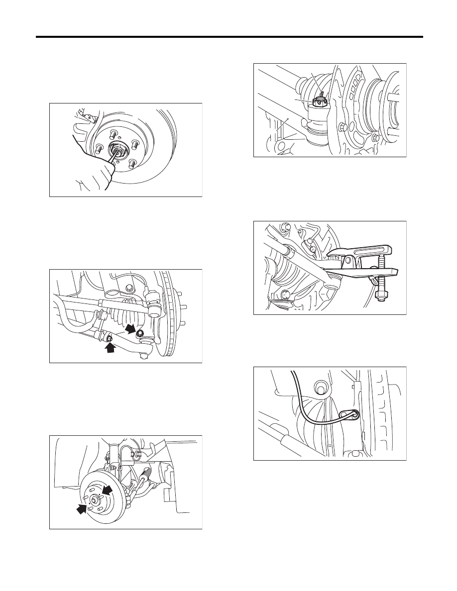
3) Lift the crimped section of axle nut.

4) Remove the axle nut using a socket wrench
while depressing the brake pedal.

CAUTION:
Remove the wheel before loosening the axle
nut. Failure to follow this rule may damage the
wheel bearings.
5) Remove the stabilizer link.

6) Remove the disc brake caliper from the housing,
and suspend it from strut using a wire.
7) Remove the disc rotor from the hub.

NOTE:
If it is difficult to remove the disc rotor from the hub,
drive the 8 mm bolt into the threaded end of rotor,
and then remove the rotor.

8) Remove the cotter pin and castle nut securing
the tie-rod end to the housing knuckle arm.

9) Using a puller, remove the tie-rod ball joint from
knuckle arm.

CAUTION:
When removing tie-rod, do not hit the tie-rod
end with hammer.
10) Remove the ABS wheel speed sensor assem-
bly and harness.

DS-00038

DS-00262

DS-00041

(A) Cotter pin

(B) Castle nut

(C) Tie-rod

DS-00042

(C)

(B)

(A)

DS-00043

DS-00249

DS-14

Front Axle

DRIVE SHAFT SYSTEM

11) Remove the bolts which secure the sensor har-
ness to the strut.

12) Remove the front arm ball joint from the housing.

13) Remove the front drive shaft from the transmis-
sion.
14) Remove the front drive shaft assembly from the
hub. If it is hard to remove, use the ST.
ST1

926470000

AXLE SHAFT PULLER

ST2

28099PA110 AXLE SHAFT PULLER PLATE

15) After scribing an alignment mark on camber ad-
justing bolt head, remove the bolts which connect
the housing and strut, and disconnect the housing
from strut.

B: INSTALLATION

1) Align the alignment mark on the camber adjust-
ing bolt head, and tighten the housing and strut us-
ing a new self-locking nut.

Tightening torque:

155 N·m (15.8 kgf-m, 114.3 ft-lb)

2) Install the front drive shaft. <Ref. to DS-22, IN-
STALLATION, Front Drive Shaft.>
3) Install the front arm ball joint to the housing.

Tightening torque:

50 N·m (5.1 kgf-m, 36.9 ft-lb)

4) Install the ABS sensor harness to the strut.
5) Install the ABS wheel speed sensor on the hous-
ing.

Tightening torque:

7.5 N·m (0.76 kgf-m, 5.5 ft-lb)

6) Install the disc rotor to hub.
7) Install the disc brake caliper on the housing.

Tightening torque:

120 N·m (12.2 kgf-m, 88.5 ft-lb)

8) Install the stabilizer link.
9) Connect the tie-rod end ball joint to the knuckle
arm with a castle nut.

Tightening torque:

27.0 N·m (2.75 kgf-m, 19.9 ft-lb)

CAUTION:
When connecting the tie-rod, do not hit the cap
at bottom of tie-rod end with a hammer.
10) Tighten the castle nut to specified torque and
tighten further within 60° until the pin hole is aligned
with the slot in nut. Bend the cotter pin to lock.

DS-00144

DS-00045

DS-00145

ST2

ST1

DS-00046

(A) Cotter pin

(B) Castle nut

(C) Tie-rod

DS-00042

(C)

(B)

(A)

DS-15

Front Axle

DRIVE SHAFT SYSTEM

11) While depressing the brake pedal, tighten a
new axle nut to the specified torque and lock it se-
curely.

Tightening torque:

220 N·m (22.4 kgf-m, 162 ft-lb)

CAUTION:
• Install the wheel after installation of axle nut.
Failure to follow this rule may damage the
wheel bearing.
• Be sure to tighten the axle nut to specified
torque. Do not overtighten it as this may dam-
age the wheel bearing.
12) After tightening the axle nut, lock it securely.

13) Install the wheel and tighten the wheel nuts to
specified torque.

Tightening torque:

120 N·m (12.2 kgf-m, 88.5 ft-lb)

C: DISASSEMBLY

1) Remove the four bolts from the housing, and re-
move the front hub unit bearing and disc cover.

CAUTION:
• Do not get closer the tool which charged
magnetism to magnetic encoder.
• Be careful not to damage the magnetic en-
coder.

2) Disassemble the front hub unit bearing. <Ref. to
DS-18, DISASSEMBLY, Front Hub Unit Bearing.>

DS-00048

(A) Housing

(1) Magnetic encoder

(2) Front hub unit bearing

DS-00231

(A)

(2)

DS-00250

(1)

DS-16

Front Axle

DRIVE SHAFT SYSTEM

D: ASSEMBLY

1) Assemble the front hub unit bearing. <Ref. to
DS-18, ASSEMBLY, Front Hub Unit Bearing.>
2) Place the disc cover between housing and front
hub unit, and tighten the four bolts.

Tightening torque:

65 N·m (6.6 kgf-m, 47.9 ft-lb)

CAUTION:
• Do not get closer the tool which charged
magnetism to magnetic encoder.
• Be careful not to damage the magnetic en-
coder.

E: INSPECTION

1) Moving the front tire up and down by hand,
check there is no backlash in bearing, and check
the wheel rotates smoothly.

2) Inspect the lean of axis direction using a dial
gauge. Replace the bearing if the load range ex-
ceeds the limitation.

Service limit:

Maximum: 0.05 mm (0.0020 in)

(A) Housing

(1) Magnetic encoder

(2) Front hub unit bearing

DS-00231

(A)

(2)

DS-00250

(1)

DS-00061

DS-00062


Content   ..  890  891  892  893   ..