Subaru Legacy IV (2008 year). Manual - part 789
5MT-52
Transmission Case
MANUAL TRANSMISSION AND DIFFERENTIAL
B: INSTALLATION
1) Wipe off grease, oil and dust on the mating sur-
faces of transmission cases with cleaning solvent.
2) Install the front differential assembly.
3) Install the main shaft assembly for single-range.
Install the transmission case knock pin into the
knock pin hole of needle bearing.
4) Install the drive pinion shaft assembly.
Install the transmission case knock pin into the roll-
er bearing knock pin hole.
5) Apply liquid gasket, then join the right side and
left side of the case together.
Liquid gasket:
THREE BOND 1215 (Part No. 004403007) or
equivalent
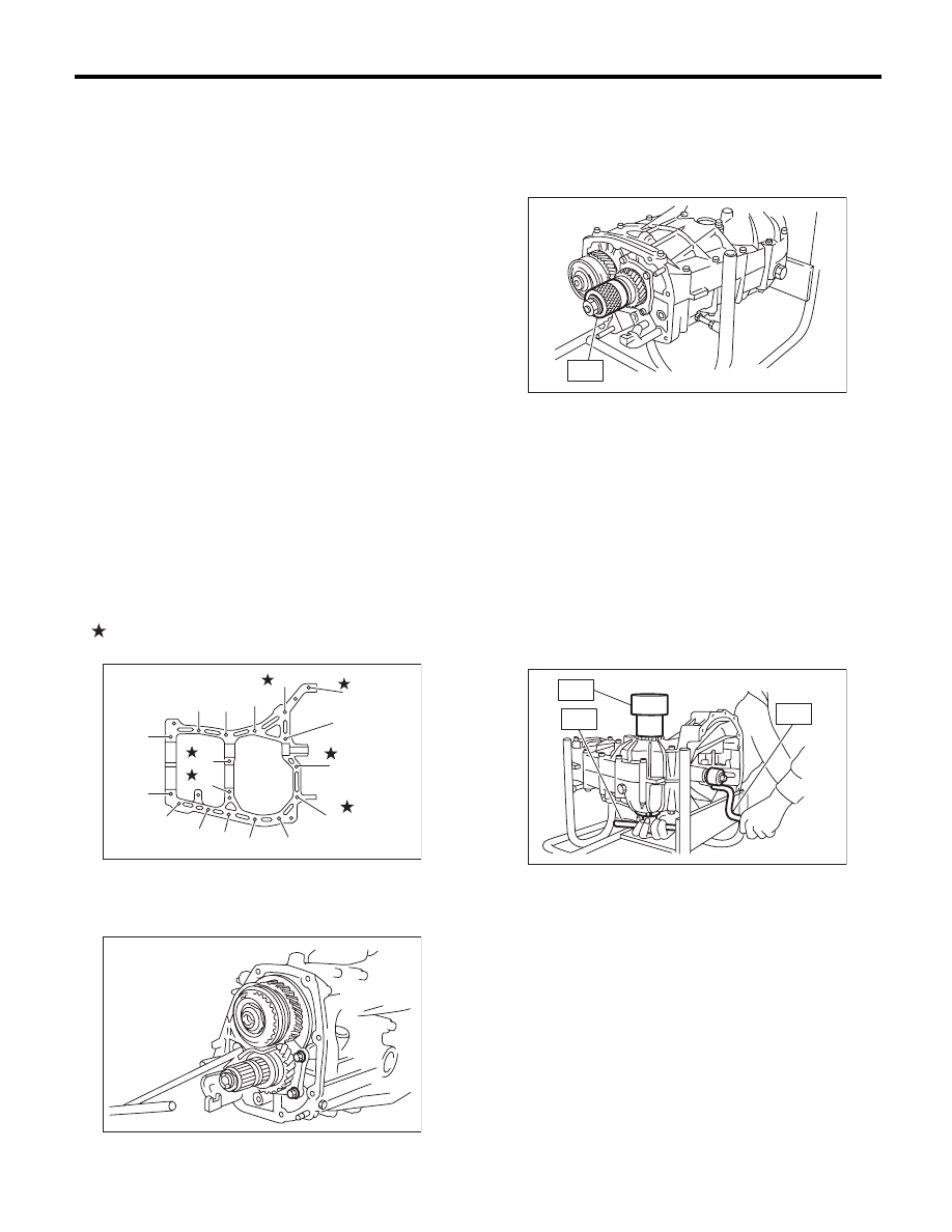
6) With brackets and clips as shown in the figure,
tighten the seventeen bolts.
NOTE:
• Insert the bolts from the bottom and tighten the
nuts at the top.
• Match the cases together so that the drive pinion
shim and input shaft holder shims are not caught
between the case halves.
Tightening torque:
8 mm bolt
25 N·m (2.5 kgf-m, 18.4 ft-lb)
10 mm bolt
39 N·m (4.0 kgf-m, 28.8 ft-lb)
7) Tighten the ball bearing mounting bolts.
Tightening torque:
30 N·m (3.1 kgf-m, 22.1 ft-lb)
8) Perform backlash adjustment of the hypoid gear
and preload measurement of the roller bearing.
NOTE:
Attach the ST on drive pinion assembly.
ST
498427100
STOPPER
9) Place the transmission with the left side of case
facing downward, and put ST1 on bearing cup.
10) Screw the retainer assembly from the bottom
into left case using ST2. Fit the ST3 on transmis-
sion main shaft. Shift the gear into 4th or 5th, and
turn the shaft several times. Screw in the retainer
while rotating the ST3 until a slight resistance is felt
on ST2.
This is the contact point of the hypoid gear and the
drive pinion shaft. Repeat the above sequence sev-
eral times to ensure the contact point.
ST1
399780104
WEIGHT
ST2
18630AA010 WRENCH COMPL RETAINER
ST3
499927100
HANDLE
MT-00172
(9)
(7)
(5)
(1)
(2)
(16)
(17)
(11)
(3)
(4)
(12)
(8)
(6)
(10)
(14)
(15)
(13)
MT-01514
ST
MT-01516
MT-00175
ST3
ST2
ST1