Subaru Legacy IV (2008 year). Manual - part 687
4AT-96
Front Differential Assembly
AUTOMATIC TRANSMISSION
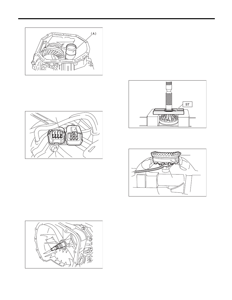
6) Install new seal pipe to converter case.
7) Install the converter case to the transmission
case. <Ref. to 4AT-81, INSTALLATION, Converter
Case.>
8) Insert the inhibitor switch connector and trans-
mission harness connector onto the stay.
9) Install the ATF cooler pipe. <Ref. to 4AT-63, IN-
STALLATION, ATF Cooler Pipe and Hose.>
10) Install the oil charge pipe together with an O-
ring. <Ref. to 4AT-66, INSTALLATION, Oil Charge
Pipe.>
11) Insert the input shaft while rotating it lightly by
hand, and then check the amount of protrusion.
Normal protrusion A:
50 — 55 mm (1.97 — 2.17 in)
12) Install the torque converter clutch assembly.
<Ref. to 4AT-67, INSTALLATION, Torque Convert-
er Clutch Assembly.>
13) Install the transmission assembly to the vehi-
cle. <Ref. to 4AT-38, INSTALLATION, Automatic
Transmission Assembly.>
C: DISASSEMBLY
1. DIFFERENTIAL CASE ASSEMBLY
1) Remove the taper roller bearing using the ST
and the press.
ST
498077000
REMOVER
2) Secure the case in a vise, remove the hypoid
driven gear tightening bolts, and then separate the
hypoid driven gear into differential case (RH) and
differential case (LH).
(A) Seal pipe
(A) Transmission harness connectors
(B) Inhibitor switch connector
A Measured value
AT-00176
AT-01351
(B)
(A)
AT-03204
A
(A) Hypoid driven gear
(B) Differential case (RH)
(C) Differential case (LH)
AT-00216
(B)
AT-00217
(A)
(C)