Subaru Legacy IV (2008 year). Manual - part 651
CS-11
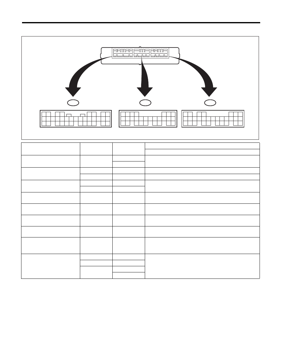
AT Shift Lock Control System
CONTROL SYSTEMS
B: ELECTRICAL SPECIFICATION
Item
Connector No.
Terminal No.
Input/Output signal
Measured value and measuring conditions
Battery power supply
B281
1
9 — 16 V
2
Ignition power supply
i84
1
10 — 15 V when ignition switch is at ON or START.
i84
24
10 — 15 V when ignition switch is at ACC.
TCM (“P” range)
B280
20
Pulse signal
B280
30
Stop light switch
B281
23
9 — 16 V when stop light switch is ON.
0 V when stop light switch is OFF.
“P” range switch
B281
13
0 V when select lever is in “P” range.
9 — 16 V when select lever is in other ranges than “P” range.
Shift lock solenoid signal
B280
6
8.5 — 16 V when shift lock is released.
0 V when shift lock is operating.
Key warning switch signal
B281
7
9 — 16 V when key is inserted.
0 V when key is removed.
Key lock solenoid signal
B280
5
7.5 — 16 V when ignition switch is turned ON, with select
lever in “P” range and brake switch ON.
0 V at other conditions than above.
Ground
B280
22
—
i84
21
B281
8
9
SL-00692
7
19
28
6
18
27
5
17
4
16
26
15
25
14
24
13 12
23
11
22
3
10
2
9
21
1
8
20
7
20
30
6
19
29
18
28
5
17
4
16
27
15
26
14 13
25
12
24
11
23
3
10
2
9
22
1
8
21
B280
B281
8
23
35
7
22
34
21
6
20
33
5
19
32
18
31
17
30
16 15
29
14
28
4
13
27
3
12
26
11
2
10
25
1
9
24
i84
A:
B:
C:
TO
TO
TO