Subaru Legacy IV (2008 year). Manual - part 495
 

  Index      Subaru     Subaru Legacy IV - service repair manual 2008 year


Search            


Content   ..  493  494  495  496   ..


Subaru Legacy IV (2008 year). Manual - part 495


CO(H6DO)-6

General Description

COOLING

C: CAUTION

• Wear appropriate work clothing, including a cap, protective goggles and protective shoes when performing
any work.
• Remove contamination including dirt and corrosion before removal, installation or disassembly.
• Keep the disassembled parts in order and protect them from dust and dirt.
• Before removal, installation or disassembly, be sure to clarify the failure. Avoid unnecessary removal, in-
stallation, disassembly and replacement.
• Vehicle components are extremely hot after driving. Be wary of receiving burns from heated parts.
• Be sure to tighten fasteners including bolts and nuts to the specified torque.
• Place shop jacks or rigid racks at the specified points.
• Before disconnecting connectors of sensors or units, be sure to disconnect the ground cable from battery.
• Prepare a container and cloth to prevent scattering of engine coolant when performing work where engine
coolant can be spilled. If the fuel spills, wipe it off immediately to prevent from penetrating into floor or flowing
out for environmental protection.
• Follow all government and local regulations concerning disposal of refuse when disposing engine coolant.

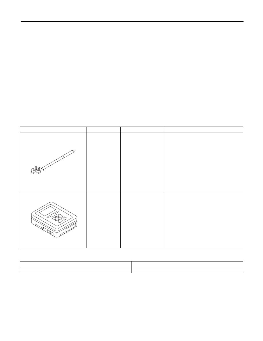
D: PREPARATION TOOL

1. SPECIAL TOOL

2. GENERAL TOOL

ILLUSTRATION

TOOL NUMBER

DESCRIPTION

REMARKS

499977100

CRANK PULLEY 
WRENCH

Used for stopping rotation of crank pulley 
when loosening and tightening crank pulley 
bolts.

1B022XU0

SUBARU SELECT 
MONITOR III KIT

Used for troubleshooting the electrical sys-
tem.

TOOL NAME

REMARKS

Radiator cap tester

Used for checking radiator and radiator cap.

ST-499977100

ST1B022XU0

CO(H6DO)-7

Radiator Fan System

COOLING

2. Radiator Fan System

A: WIRING DIAGRAM

CO-02254

3

1

2

B136

ECM

16

F108

F106

7

B361

1
7

F108

2 3

8

10

1

9

4

11 12 13 14 15 16

5 6 7

17 18

B361

1
7

2 3

4 5 6

8 9 10 11 12 13 14

29

18

F106

1 2 3

B7

E

SBF-6

MAIN SBF

No.2

No.26

B143

B:

F36

E:

E6

3

1 2

7

4 5

6

F36

E:

B143

1 2 3 4

5 6 7

12 13 14 15 16 17 18

B:

8

19

11

9

20

10

E

M

M

MAIN FAN RELAY 1

MAIN FUSE BOX (M/B)

F17

1

2

F17

1 2

B136

16

10 11 12 13 14 15

25

24

30

9

8

7

17 18 19 20
28

21 22 23

29

32

31

1

2

3

4

5

6

27

26

33 34 35

MAIN FAN MOTOR

SUB FAN MOTOR

THROUGH JOINT CONNECTOR

RADIATOR FAN 
CONTROL UNIT

IGNITION SWITCH

CO(H6DO)-8

Radiator Fan System

COOLING

B: RADIATOR FAN CONTROL OUTPUT WAVEFORM

C: INSPECTION

DETECTING CONDITION:
• Engine coolant temperature is 93°C (199°F) or more.
• A/C switch is turned OFF.
• Vehicle speed is 19 km/h (12 MPH) or less.
TROUBLE SYMPTOMS:
Radiator main and sub fans do not rotate under the above conditions.

(A)

V


Step

Check

Yes

No

1

CHECK MAIN FAN RELAY 1.
1) Turn the ignition switch to OFF.
2) Remove main fan relay 1 from the main fuse 
box.
3) Measure the resistance of terminal in main 
fan relay 1 switch.

Is the resistance 1 M

: or 

more?

Go to step 2.

Replace the main 
fan relay 1.

2

CHECK MAIN FAN RELAY 1.
1) Connect the main fan relay 1 coil side termi-
nal to the battery.
2) Measure the resistance between terminals 
of main fan relay 1 switch.

Is the resistance less than 1 

:? Go to step 3.

Replace the main 
fan relay 1.

3

CHECK POWER SUPPLY FOR ECM.
1) Disconnect the connectors from ECM.
2) Turn the ignition switch to ON.
3) Measure the voltage between ECM connec-
tor and chassis ground.

Connector & terminal

(B136) No. 29 (+) — Chassis ground (–):

Is the voltage 10 V or more?

Go to step 4.

Repair the power 
supply line.

CO-02117

(V)

0

(A)

CO(H6DO)-9

Radiator Fan System

COOLING

4

CHECK POWER SUPPLY FOR RADIATOR 
FAN CONTROL UNIT.
1) Turn the ignition switch to OFF.
2) Connect the connector to ECM.
3) Disconnect the connector from radiator fan 
control unit.
4) Turn the ignition switch to ON.
5) Measure the voltage between radiator fan 
control unit connector and chassis ground.

Connector & terminal

(F106) No. 1 (+) — Chassis ground (–):

Is the voltage 10 V or more?

Go to step 5.

Repair the power 
supply line.

5

CHECK HARNESS BETWEEN ECM AND RA-
DIATOR FAN CONTROL UNIT.
1) Turn the ignition switch to OFF.
2) Disconnect the connectors from ECM.
3) Measure the resistance of harness between 
radiator fan control unit and ECM connector.

Connector & terminal

(B136) No. 18 — (F106) No. 2:

Is the resistance less than 1 

:? Go to step 6.

Repair the open 
circuit of harness 
between ECM and 
radiator fan control 
unit.

6

CHECK RADIATOR FAN CONTROL UNIT 
AND GROUND CIRCUIT.
1) Connect the connector to ECM and radiator 
fan control unit.
2) Measure the resistance between radiator 
fan control unit connector and chassis ground.

Connector & terminal

(F106) No. 3 — Chassis ground:

Is the resistance less than 5 

:? Go to step 7.

Repair the open 
circuit of harness 
between radiator 
fan control unit 
connector and 
chassis ground.

7

CHECK FAN MOTOR.
1) Disconnect the connector from radiator fan 
control unit.
2) Connect the battery positive (+) terminal to 
terminal No. 1 of the radiator fan control unit, 
and the ground (–) terminal to terminal No. 3.

Does the fan motor rotate?

Go to step 8.

Replace the fan 
motor which does 
not rotate.

8

CHECK OUTPUT SIGNAL FROM ECM.
1) Connect the delivery (test) mode connector.
2) Turn the ignition switch to ON.
3) Check the output waveform using oscillo-
scope. <Ref. to CO(H6DO)-8, RADIATOR FAN 
CONTROL OUTPUT WAVEFORM, Radiator 
Fan System.>

Connector & terminal

(B136) No. 18 (+) — Chassis ground (–):

Is a waveform output?

Replace the radia-
tor fan control unit. 
<Ref. to 
CO(H6DO)-25,
Radiator Fan Con-
trol Unit.>

Replace the ECM. 
<Ref. to 
FU(H6DO)-38, 
Engine Control 
Module (ECM).>

Step

Check

Yes

No


Content   ..  493  494  495  496   ..