Subaru Legacy IV (2008 year). Manual - part 485


  Index      Subaru     Subaru Legacy IV - service repair manual 2008 year


Search            


Content   ..  483  484  485  486   ..


Subaru Legacy IV (2008 year). Manual - part 485


ME(H6DO)-66

Cylinder Block

MECHANICAL

B: INSTALLATION

1) After setting the cylinder block to ST, install the
crankshaft bearing.
ST

18232AA000

ENGINE STAND

NOTE:
Remove oil on the mating surface of cylinder block
before installation. Apply a coat of engine oil to the
bearing and crankshaft journal.
2) Position the crankshaft on the cylinder block
(RH).
3) Apply liquid gasket to the mating surfaces of cyl-
inder block (RH), and position the cylinder block
(LH).

NOTE:
• Do not allow liquid gasket to run over to oil pas-
sages, bearing grooves, etc.
• Install within 5 minutes after applying liquid gas-
ket.

Liquid gasket:

THREE BOND 1217G (Part No. K0877Y0100) 
or equivalent

Applying liquid gasket diameter:

1.0

r

0.2 mm (0.039

r

0.008 in)

4) Apply a coat of engine oil to the washer and bolt
thread.
5) Tighten all bolts in the numerical order as shown
in the figure.

Tightening torque:

(1) — (11), (13): 25 N·m (2.5 kgf-m, 18.4 ft-lb)
(12), (14): 20 N·m (2.0 kgf-m, 14.8 ft-lb)

6) Retighten all bolts in the numerical order as
shown in the figure.

Tightening torque:

(1) — (11), (13): 25 N·m (2.5 kgf-m, 18.4 ft-lb)
(12), (14): 20 N·m (2.0 kgf-m, 14.8 ft-lb)

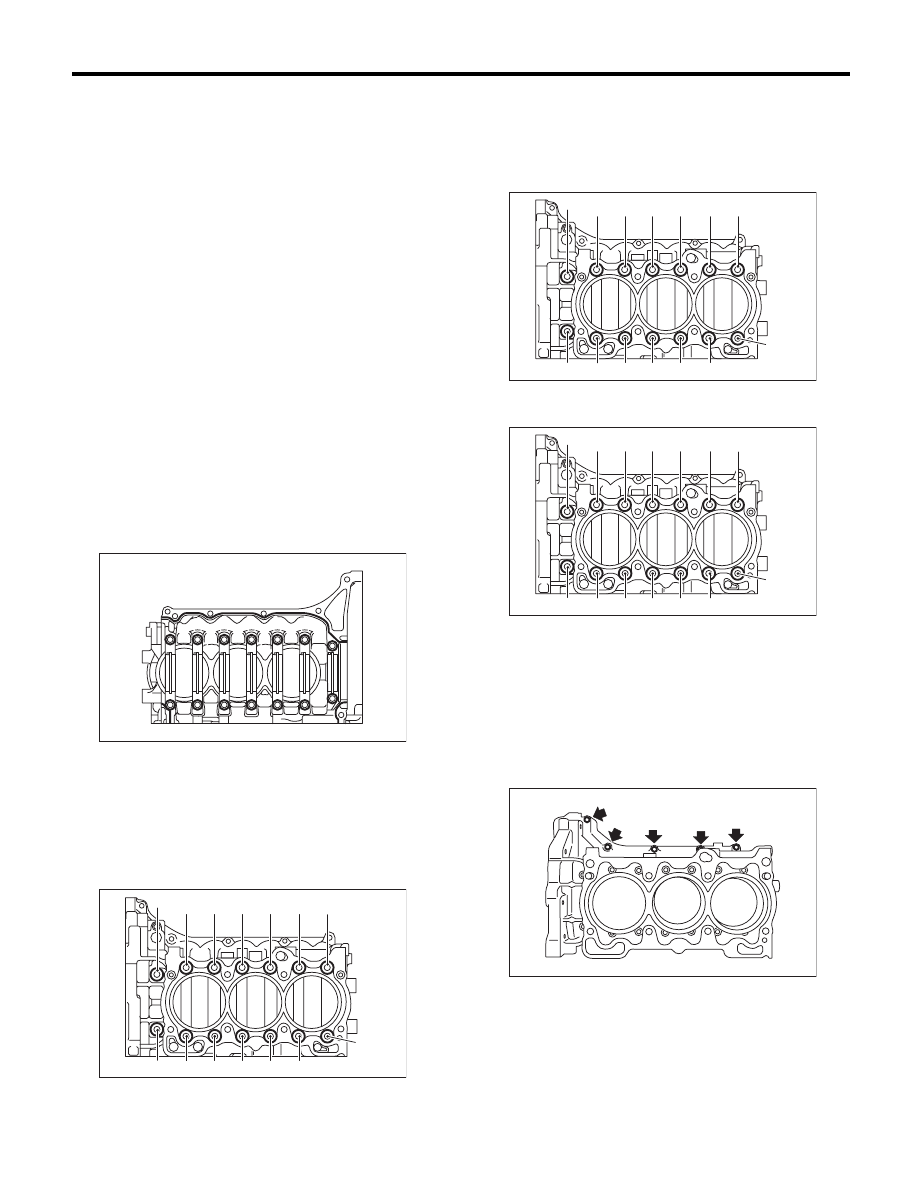
7) Tighten all bolts 90° — 110° in the numerical or-
der as shown in the figure.

8) Install the upper bolt to cylinder block.

Tightening torque:

25 N·m (2.5 kgf-m, 18.4 ft-lb)

NOTE:
After tightening the cylinder block connecting bolts,
remove the liquid gasket which is running over to
the sealing surface for rear chain cover and oil pan
upper.

ME-00567

(1)

(6)

(8)

(3)

(9)

(2)

(4)

(5)

(7)

(10)

(11)

(12)

(13)

(14)

ME-00568

(1)

(6)

(8)

(3)

(9)

(2)

(4)

(5)

(7)

(10)

(11)

(12)

(13)

(14)

ME-00568

(1)

(6)

(8)

(3)

(9)

(2)

(4)

(5)

(7)

(10)

(11)

(12)

(13)

(14)

ME-00568

ME-00569

ME(H6DO)-67

Cylinder Block

MECHANICAL

9) Apply a coat of engine oil to the oil seal periph-
ery, then install the rear oil seal using ST1 and ST2.

NOTE:
Use new rear oil seal.
ST1

499597100

CRANKSHAFT OIL SEAL 
GUIDE

ST2

499587200

CRANKSHAFT OIL SEAL 
INSTALLER

10) Position the top ring gap at (A) in the figure.
11) Position the second ring gap at (B).

12) Position the upper rail gap at (C) in the figure.
13) Position the expander gap at (D) in the figure.
14) Position the lower rail gap at (E) in the figure.

CAUTION:
• Make sure ring gaps do not face the same di-
rection.
• Make sure ring gaps are not within the piston
skirt area.
• Assemble it so that R mark faces to top side
of piston.

15) Install the snap ring.
Install the snap rings in the piston holes located op-
posite to the service holes in cylinder block when
positioning all pistons in corresponding cylinders.

NOTE:
Use new snap rings.

16) Installing piston:

(1) Using ST1, turn the crankshaft so that #3
and #4 connecting rod small ends are set on the
service hole (A).

ST1

18252AA000 CRANKSHAFT SOCKET

(2) Apply a thin coat of engine oil to piston and
cylinder.

(A) Rear oil seal

(B) Drive plate installation bolt

ST2

ST1

(A)

(B)

ME-00570

180˚

(A)

(B)

ME-02066

25˚

35˚

(C)

(D)

(E)

ME-02067

(A) Front side of vehicle

(A)

#1

#2

#3

#4

#5

#6

ME-00573

ST1

(A)

(A)

ME-00574

ME(H6DO)-68

Cylinder Block

MECHANICAL

(3) Using ST2, press-fit the piston into cylinder.

ST2

18254AA000 PISTON GUIDE

NOTE:
Let the piston front mark (A) face towards the front
of engine.

17) Installing piston pin:

(1) Apply a coat of engine oil to ST3 before in-
sertion, and then insert it into the service hole to
align piston pin hole with connecting rod small
end.

ST3

18253AA000 PISTON PIN GUIDE

(2) Apply a coat of engine oil to piston pin, and
insert the piston pin into piston and connecting
rod through service hole.

(3) Using ST4, install the snap ring.

ST4

18233AA000 PISTON PIN SNAP RING 

PLIERS

NOTE:
Use new snap rings.

(4) Similarly install the #1, #2, #5 and #6 pis-
tons.

18) Install the service hole plug and O-ring.

NOTE:
Use new O-rings.
19) Apply liquid gasket to the mating surface of oil
pan upper.

NOTE:
Install within 5 minutes after applying liquid gasket.

Liquid gasket:

THREE BOND 1217G (Part No. K0877Y0100) 
or equivalent

Applying liquid gasket diameter:

Full line part

3.0

r

1.0 mm (0.12

r

0.04 in)

Broken line part

1.0 mm (0.04 in)

NOTE:
Use new O-rings.

ST2

ME-00576

(A)

ME-02076

ST3

ME-00577

(A) O-ring

ST4

ME-00564

ME-02068

(A)

(A)

(A)

(A)

ME(H6DO)-69

Cylinder Block

MECHANICAL

20) Temporarily tighten the oil pan upper.

NOTE:
Do not install the bolts in wrong place.

21) Tighten the oil pan upper installing bolts in the
numerical order as shown in the figure.

Tightening torque:

18 N·m (1.8 kgf-m, 13.3 ft-lb)

22) Install the oil strainer.

Tightening torque:

6.4 N·m (0.7 kgf-m, 4.7 ft-lb)

NOTE:
Use new O-rings.

23) Apply liquid gasket to the matching surface of
oil pan lower.

NOTE:
Install within 5 minutes after applying liquid gasket.

Liquid gasket:

THREE BOND 1217G (Part No. K0877Y0100) 
or equivalent

Applying liquid gasket diameter:

5.0

r

1.0 mm (0.20

r

0.04 in)

(A) M8 × 40

(B) M8 × 65

(C) M8 × 85

(D) M8 × 130.5

(E) M8 × 24

*: Coating

ME-02069

(D)

(E)

(A)

(A)

(A)

(A)

(A)

(A)

(A)

(E)

(A)

(A)

(A)

(C)

(B)

(A)

(D)

(A)

(A)

(A)

(A)

(A)

(B)

ME-02070

(19)

(14)

(12)

(16)

(24)

(22)

(27)

(25)

(21)

(17)

(13)

(11)

(15)

(23)

(26)

(20)

(18)

(7)

(6)

(9)

(8) (10)

(5)

(3)

(4)

(1)

(2)

LU-02108

ME-00581


Content   ..  483  484  485  486   ..