Subaru Legacy IV (2008 year). Manual - part 347
 

  Index      Subaru     Subaru Legacy IV - service repair manual 2008 year


Search            


Content   ..  345  346  347  348   ..


Subaru Legacy IV (2008 year). Manual - part 347


EN(H4DOTC)(diag)-209

Diagnostic Procedure with Diagnostic Trouble Code (DTC)

ENGINE (DIAGNOSTICS)

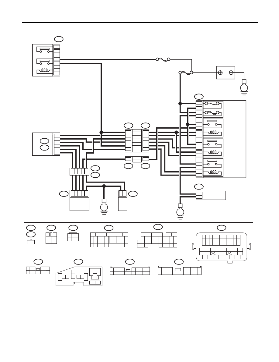
WIRING DIAGRAM:

EN-05678

B47

1

2

4

6

3

5

SBF-7

E

F9

13

12

11

14

1

2

2

1

3

4

16

15

5

6

B143

F37

B144

B21

E2

E41

E40

B134

A:

B136

C:

F37

F11

B21

E40

B47

B144

F9

B143

F37

E41

1 2 3 4

12 13 14 15

5 6 7 8

16 17 18 19

9 10 11

20 21 22

23 24 25 26 27 28 29 30 31 32 33

35

34

37

36

39

38

41

40

43

42

44

45

47

46

49

48

51

50

53

52

54

MAIN
SBF

10A

60A

9

10

8

7

E

E

11

5

20

8

C30
C19

C8

A19
A27
A29

6

1

28

47

3

2

1

6

4

1

2

9
2

16
18

14
12
10

4

14

4

F11

1 2

3

4

1

2

5

6

1

3

4 5 6

2

B134

5

6

7

8

2

1

9

4

3

10

24

22 23

25

11 12 13 14 15

26 27

28

16 17

18 19 20 21

33 34

29

32

30 31

16

10 11 12 13 14 15

25

24

30

9

8

7

17 18 19 20
28

21 22 23

29

32

31

1

2

3

4

5

6

27

26

33 34 35

B136

1
5

7

6

2

8

3

4
9

1 2 3 4

5 6 7 8 9

10 11 12 13 14

15 16 17 18 19 20

1 2 3 4

5 6 7 8 9

10 11 12 13 14 15 16 17 18 19 20

5

6

3

1
2

9

10

12

11

13

14

4

7 8

15

16

46

MAIN RELAY

BATTERY

RELAY HOLDER

SECONDARY 
AIR
COMBINATION 
VALVE RELAY1

SECONDARY 
AIR
COMBINATION 
VALVE RELAY2

SECONDARY 
AIR PUMP
RELAY

SECONDARY 
AIR PUMP

MAIN FUSE 
BOX (M/B)

ECM

SECONDARY AIR 

COMBINATION VALVE  RH

(WITH BUILT-IN PRESSURE SENSOR)

SECONDARY AIR 

COMBINATION 

VALVE LH

EN(H4DOTC)(diag)-210

Diagnostic Procedure with Diagnostic Trouble Code (DTC)

ENGINE (DIAGNOSTICS)

Step

Check

Yes

No

1

CHECK HARNESS BETWEEN ECM AND 
SECONDARY AIR PUMP RELAY.
1) Turn the ignition switch to OFF.
2) Disconnect the connector from the ECM 
and secondary air pump relay.
3) Measure the resistance of the harness 
between the ECM and secondary air pump 
relay.

Connector & terminal

(B136) No. 8 — (F9) No. 13:

Is the resistance less than 1 

:? Go to step 2.

Repair the harness 
and connector.

NOTE:
In this case, repair
the following item:
• Open circuit in
harness between
ECM and second-
ary air pump relay
• Poor contact of
coupling connector

2

CHECK HARNESS BETWEEN ECM AND 
SECONDARY AIR PUMP RELAY.
Measure the resistance between ECM and 
chassis ground.

Connector & terminal

(B136) No. 8 — Chassis ground:

Is the resistance 1 M

: or 

more?

Even if DTC is 
detected, the cir-
cuit has returned to 
a normal condition 
at this time. Repro-
duce the failure, 
and then perform 
the diagnosis 
again.

NOTE:
In this case, tem-
porary poor con-
tact of connector
may be the cause.

Repair ground 
short circuit of the 
harness between 
the ECM and sec-
ondary air pump 
relay.

EN(H4DOTC)(diag)-211

Diagnostic Procedure with Diagnostic Trouble Code (DTC)

ENGINE (DIAGNOSTICS)

BJ:DTC P0420 CATALYST SYSTEM EFFICIENCY BELOW THRESHOLD (BANK 1)

DTC DETECTING CONDITION:
• Two consecutive driving cycles with fault
• GENERAL DESCRIPTION <Ref. to GD(H4DOTC)-105, DTC P0420 CATALYST SYSTEM EFFICIENCY
BELOW THRESHOLD (BANK 1), Diagnostic Trouble Code (DTC) Detecting Criteria.>
TROUBLE SYMPTOM:
• Engine stalls.
• Idle mixture is out of specifications.

CAUTION:
After repair or replacement of faulty parts, perform Clear Memory Mode <Ref. to EN(H4DOTC)(diag)-
52, OPERATION, Clear Memory Mode.>, and Inspection Mode <Ref. to EN(H4DOTC)(diag)-43, PRO-
CEDURE, Inspection Mode.>.
WIRING DIAGRAM:

EN-05670

B83

1 2 3 4
5 6 7 8

B138

B47

1

2

4

6

3

5

E

*

*

B138

B83

3

4

1

2

5

6

B135

B47

B19

B136

B:

C:

B137

D:

5

6

7 8

2

1

9

4

3

10

24

22 23

25

11 12 13 14 15

26 27

28

16

17 18 19 20 21

33 34

29

32

30

31

35

5

6

7

8

2

1

9

4

3

10

24

22 23

25

11 12 13 14 15

26 27

28

16 17 18 19

20 21

29 30 31

32 33

34 35

5

6

7

8

2

1

9

4

3

10

22 23

11 12 13 14 15

24 25

26

16 17

18 19 20 21

27

28 29

30 31

B19

T5

2

2

T5

B19

3

1

4

B21

1 2 3 4

12 13 14 15

5 6 7 8

16 17 18 19

9 10 11

20 21 22

23 24 25 26 27 28 29 30 31 32 33

35

34

37

36

39

38

41

40

43

42

44

45

47

46

49

48

51

50

53

52

54

T6

SBF-5

*

1

*

2

1
1

*

*

2
2

C4

B4

B30

B1

B134

T6

B134

5

6

7

8

2

1

9

4

3

10

24

22 23

25

11 12 13 14 15

26 27

28

16 17

18 19 20 21

33 34

29

32

30 31

A:

B135

B:

B136

C:

B137

D:

A:

D2

A5

D3

E2

B21

E

35

34

40

D7

36

D1

37

1 2
3 4

3

1

4

MAIN RELAY

REAR
OXYGEN SENSOR

BATTERY

ECM

: TERMINAL No. OPTIONAL 
  ARRANGEMENT

: TERMINAL No. OPTIONAL 
  ARRANGEMENT 
  AMONG 1, 2, 5  AND 6

EN(H4DOTC)(diag)-212

Diagnostic Procedure with Diagnostic Trouble Code (DTC)

ENGINE (DIAGNOSTICS)

Step

Check

Yes

No

1

CHECK EXHAUST SYSTEM.
Check for gas leaks or air suction caused by 
loose or dislocated nuts and bolts, and open 
hole at exhaust pipes.

NOTE:
Check the following positions.
• Between cylinder head and front exhaust
pipe
• Between front exhaust pipe and front catalytic
converter
• Between front catalytic converter and rear
catalytic converter
• Looseness and improper attachment of front
oxygen (A/F) sensor or rear oxygen sensor

Is there any fault in exhaust 
system?

Repair or replace 
the exhaust sys-
tem. <Ref. to 
EX(H4DOTC)-2, 
General Descrip-
tion.>

Go to step 2.

2

CHECK WAVEFORM DATA ON THE SUBA-
RU SELECT MONITOR (WHILE DRIVING).
1) Drive at a constant speed between 80 — 
112 km/h (50 — 70 MPH).
2) After 5 minutes have elapsed in the condi-
tion of step 1), use the Subaru Select Monitor 
while still driving to read the waveform data.
• At normal condition

• At abnormal condition (numerous inversion)

Is normal waveform pattern dis-
played?

Even if DTC is 
detected, the cir-
cuit has returned to 
a normal condition 
at this time. Repro-
duce the failure, 
and then perform 
the diagnosis 
again.

NOTE:
In this case, tem-
porary poor con-
tact of connector
may be the cause.

Go to step 3.

EN-06666

1

0

1.5

0.5

10 sec/div

REAR OXYGEN 
SENSOR VOLTAGE 
                           (V)

A/F SENSOR 
OUTPUT LAMBDA 1

EN-06667

1

0

1.5

0.5

10 sec/div

REAR OXYGEN 
SENSOR VOLTAGE 
                           (V)

A/F SENSOR 
OUTPUT LAMBDA 1


Content   ..  345  346  347  348   ..