Subaru Legacy IV (2008 year). Manual - part 99
SC(H4SO)-20
Battery
STARTING/CHARGING SYSTEMS
4. Battery
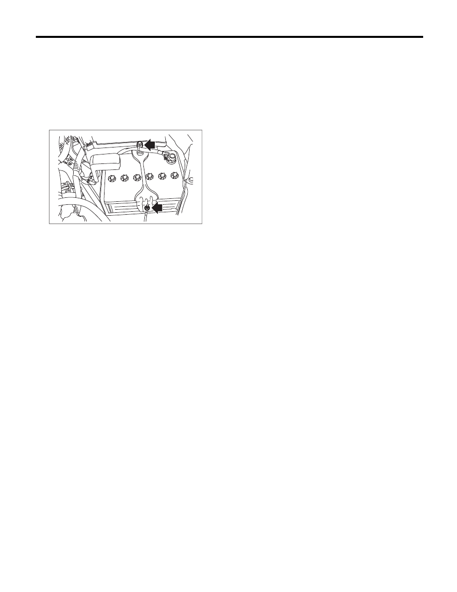
A: REMOVAL
1) Disconnect the positive (+) terminal after discon-
necting the negative (–) terminal of battery.
2) Remove the harness clip of the negative termi-
nal from the battery rod.
3) Remove the flange nut from battery rod and re-
move battery holder.
4) Remove the battery.
B: INSTALLATION
Install in the reverse order of removal.
Tightening torque:
3.5 N·m (0.4 kgf-m, 2.6 ft-lb)
NOTE:
• Clean the battery cable terminals and apply
grease to retard the formation of corrosion.
• Connect the battery positive (+) terminal, and
then connect the negative (–) terminal.
• After the battery is installed, initial diagnosis of
the electronic throttle control is performed. Wait for
10 seconds or more after turning the ignition switch
to ON, and then start the engine.
C: INSPECTION
WARNING:
• Electrolyte is corrosive acid, and has toxici-
ty; be careful of handling the fluid.
• Make sure the electrode does not come into
contact with skin, eyes or clothing. Especially
at contact with eyes, flush with water for 15
minutes and get prompt medical attention.
• In addition, be careful not to let the electrode
contact with the coated parts.
• Be careful when handling the batteries be-
cause they produce explosive gases.
• Be sure to keep battery away from any fire.
• For safety, in case an explosion does occur,
wear eye protection or shield your eyes when
working near any battery. In addition, never
lean over the battery.
• Ventilate sufficiently when using or charging
battery in enclosed space.
• Before starting work, remove rings, metal
watch-bands, and other metal jewelry.
• Never allow metal tools to contact the posi-
tive battery terminal and anything connected to
it while you are at the same time in contact with
any other metallic portion of the vehicle.
1. EXTERNAL PARTS
Check the battery case, top cover, vent plugs, and
terminal posts for dirt or cracks. If necessary, clean
with water and wipe with a dry cloth.
Apply a thin coat of grease on the terminal posts to
prevent corrosion.
2. ELECTROLYTE LEVEL
Check the electrolyte level in each cell. If the level
is below MIN level, bring the level to MAX level by
pouring distilled water into the battery cell. Do not
fill beyond MAX level.
SC-02238