Subaru Legacy IV (2008 year). Manual - part 25


  Index      Subaru     Subaru Legacy IV - service repair manual 2008 year


Search            


Content   ..  23  24  25  26   ..


Subaru Legacy IV (2008 year). Manual - part 25


PM-40

Brake Line

PERIODIC MAINTENANCE SERVICES

3) Check the pedal stroke.
While the engine is idling, depress the brake pedal
with a 490 N (50 kgf, 110 lb) load and measure the
distance between the brake pedal and steering
wheel. With the brake pedal released, measure the
distance between pedal and steering wheel again.
The pedal stroke is normal if the difference be-
tween two measured values is the specified value
or less. If the measured value is the specification or
more, there is possibility of entering air in hydraulic
unit.

Brake pedal stroke A:

95 mm (3.7 in)/ 490 N (50 kgf, 110 lb) or less

4) Check to see if air is in the hydraulic brake line
by the feel of pedal operation. If air appears to exist
in the line, bleed it from the system.
5) Check for even operation of all brakes, using a
brake tester or by driving the vehicle for a short dis-
tance on a straight road.

3. BRAKE SERVO SYSTEM

1) With the engine off, depress the brake pedal
several times applying the same pedal force. Make
sure the travel distance should not change.
2) With the brake pedal depressed, start the en-
gine. Make sure the pedal should move slightly to-
ward the floor.
3) With the brake pedal depressed, stop the engine
and keep the pedal depressed for 30 seconds.
Make sure the pedal height should not change.
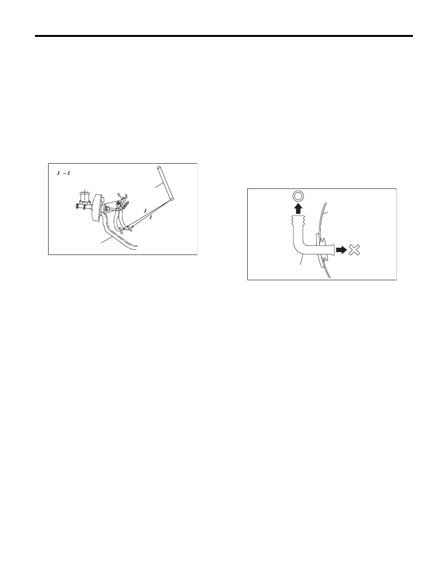
4) A check valve is incorporated into the brake
booster nipple part. Disconnect the vacuum hose to
inspect function of check valve.
Make sure air flows from the booster end to engine
end but does not flow in the opposite direction in
the check valve.

5) Check the vacuum hose for cracks or other dam-
age.

NOTE:
When installing the vacuum hose on the engine
and brake booster, do not use soapy water or lubri-
cating oil on their connections.
6) Check the vacuum hose to make sure it is tightly
secured.

(A) Steering wheel

(B) Toe board

PM-00045

(B)

(A)

= A

1

1

2

2

(A) Brake booster

(B) Check valve

(C) Engine side

(D) Brake booster side

PM-00260

(D)

(A)

(C)

(B)

PM-41

Brake Fluid

PERIODIC MAINTENANCE SERVICES

17.Brake Fluid

A: REPLACEMENT

1) Either jack-up the vehicle and place a rigid rack
under it, or lift up the vehicle.
2) Remove all the wheels.
3) Drain the brake fluid from master cylinder.
4) Refill the reservoir tank with recommended
brake fluid.

CAUTION:
If brake fluid is spilt on the exhaust pipe, wipe it
off with a cloth to avoid emitting smoke or
causing a fire.

Recommended brake fluid:

Refer to RM section. <Ref. to RM-4, FLUID, 
RECOMMENDED MATERIALS, Recommend-
ed Materials.>

NOTE:
• Avoid mixing different brands of brake fluid to
prevent degrading the quality of fluid.
• Be careful not to allow dirt or dust to get into the
reservoir tank.
• Perform the operation in the order from farthest
wheel cylinder to the master cylinder.
5) Install one end of a vinyl tube onto the air bleeder
and insert the other end of the tube into a container
to collect the brake fluid.

NOTE:
• Cover the bleeder with cloth, when loosening it,
to prevent brake fluid from being splashed over sur-
rounding parts.
• While bleeding air, keep the reservoir tank filled
with brake fluid to prevent entry of air.
• Operate the brake pedal slowly.
• For convenience and safety, perform work with 2
people.
• The amount of brake fluid required is approx.
500 m

2 (16.9 US fl oz, 17.6 Imp fl oz) for total

brake system.
6) Instruct your co-worker to depress the brake
pedal slowly two or three times and then hold it de-
pressed.

7) Loosen the bleeder screw approximately 1/4
turn until a small amount of brake fluid drains into
the container, and then quickly tighten the screw.
8) Repeat steps 6) and 7) until there are no air bub-
bles in drained brake fluid and new fluid flows
through vinyl tube.

NOTE:
Add brake fluid as necessary while performing the
air bleed operation, in order to prevent the tank
from running short of brake fluid.
9) After completing the bleeding operation, hold the
brake pedal depressed and tighten the screw and
install bleeder cap.

Tightening torque:

8 N·m (0.8 kgf-m, 5.8 ft-lb)

10) Bleed air from each wheel cylinder by following
steps from 5) to 9).
11) Depress the brake pedal with a force of approx.
294 N (30 kgf, 66 lb) and hold it there for approx. 20
seconds. At this time check the pedal to see if it
makes any unusual movement. Visually inspect the
bleeder screws and brake pipe joints to confirm
there is no fluid leakage.
12) Install the wheels, and drive the vehicle for a
distance of 2 to 3 km (1 to 2 miles) to confirm that
brakes are operating properly.

PM-00048

PM-42

Disc Brake Pad and Disc

PERIODIC MAINTENANCE SERVICES

18.Disc Brake Pad and Disc

A: INSPECTION

1) Jack-up the vehicle and support with rigid racks.
Then remove the wheels.
2) Visually check the pad thickness through inspec-
tion hole of disc brake assembly. Replace the pad if
necessary.

NOTE:
When replacing a pad, always replace the pads for
both the left and right wheels at the same time. Also
replace the pad clips if they are twisted or worn.

• Front

• Rear

3) Check the disc rotor, and correct or replace if it is
damaged or worn.
• Front

• Rear

4) Remove the caliper body. <Ref. to BR-15, Front
Disc Brake Assembly.> <Ref. to BR-22, Rear Disc
Brake Assembly.>
5) Tighten the wheel nuts to secure disc rotor.
6) Set a dial gauge at a point of 10 mm (0.39 in) or
less from outer periphery of the rotor, and then
measure the disc rotor runout.

Disc rotor runout limit:

Front: 0.05 mm (0.002 in)
Rear: 0.05 mm (0.002 in)

(A) Inspection hole

Pad thickness

mm (in)

Standard

16-inch

11 (0.43)

17-inch

11 (0.43)

Wear limit

16-inch

1.5 (0.059)

17-inch

1.5 (0.059)

Pad thickness

mm (in)

Standard

Solid disc type

9 (0.35)

Ventilated disc type

9 (0.35)

Wear limit

Solid disc type

1.5 (0.059)

Ventilated disc type

1.5 (0.059)

(A) Pad thickness

(B) Back metal

(C) Lining

PM-00049

(A)

PM-00140

(A)

(C)

(B)

Disc rotor thickness

mm (in)

Standard

16-inch

24 (0.94)

17-inch

30 (1.18)

Wear limit

16-inch

22 (0.87)

17-inch

28 (1.10)

Disc rotor thickness

mm (in)

Standard

Solid disc type

10 (0.39)

Ventilated disc type

18 (0.71)

Wear limit

Solid disc type

8.5 (0.34)

Ventilated disc type

16 (0.63)

PM-00051

PM-43

Parking Brake

PERIODIC MAINTENANCE SERVICES

19.Parking Brake

A: INSPECTION

Inspect the brake linings and disc rotor of both
sides of the rear brake at the same time by remov-
ing disc rotor.
1) Inspect the brake shoes for damage or deforma-
tion and check the brake linings for wear.

NOTE:
Always replace both primary and secondary brake
shoes for the left and right wheels at the same time.

Thickness of brake lining (except for back metal):

Standard: 3.2 mm (0.126 in)
Wear limit: 1.5 mm (0.059 in)

2) Check the inside of disc rotor for wear, dents or
other damage. If the inside surface of dick rotor is
streaked, correct the surface with emery cloth
(#200 or more). If it is unevenly worn or tapered,
correct or replace it.

Brake drum inside diameter:

Standard: 170 mm (6.69 in)
Wear limit: 171 mm (6.73 in)

3) If the deformation or wear of back plate, shoe,
etc. is noticeable, replace them.

4) When the shoe return spring tension is exces-
sively weakened, replace it.

B: ADJUSTMENT

For rear disc brake, adjust the parking brake after
bleeding air.
1) Remove the rear cover (rubber) installed at back
plate.
2) Turn the adjuster toward arrow mark (upward)
until it is locked slightly, by using flat-tip screwdriver
as shown in the figure.

3) Turn back (downward) the adjuster 3 to 4 notch-
es.
4) Install the cover (rubber) in original position cor-
rectly.

(A) Forward

(B) Brake shoe (Primary side)

(C) Brake shoe (Secondary side)

(A) Inside diameter

(B) Disc

PM-00054

(B)

(C)

(A)

PM-00055

(A)

(B)

(A) Adjuster

(B) Cover (rubber)

(C) Back plate

PM-00056

(B)

(C)

(A)


Content   ..  23  24  25  26   ..