Subaru BRZ Electrical Manual - part 2
B
[A] : System Title
[B] : Indicates a Relay Block. No shading is used and
only the Relay Block No. is shown to distinguish it
from the J/B
Example: Indicates Relay Block No.1
[C] : ( ) is used to indicate different wiring and
connector, etc. when the vehicle model, engine
type, or specification is different.
[D] : Indicates related system.
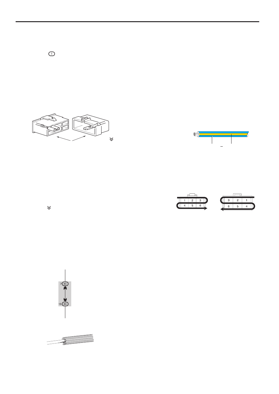
[E] : Indicates the code for the (male and female)
connectors which are used to join two wire
harnesses. The connector code consists of two
alphabetical and one numerical characters.
Female
Male ( )
The first character of the connector code indicates
the alphabetical code allocated to the wire harness
which has the female connector, and the second
shows that of the wire harness which has the male
connector.
The third character indicates a serial number used
to distinguish between the wire harness
combinations in cases when more than one of the
same combination of wire harnesses exist
(e.g. CH1 and CH2).
Symbol ( ) indicates the male terminal connector.
Numbers outside connector codes indicate the pin
numbers of both male and female connectors.
[F] : Represents a part (all parts are shown in sky blue).
The code is the same as the code used in parts
position.
[G] : Junction Block (The number in the circle is the J/B
No. and the connector code is shown beside it).
Junction Blocks are shaded to clearly separate
them from other parts.
3C indicates that
it is inside
Junction Block
No.3
Example:
[I]
: Indicates the wiring color.
Wire colors are indicated by an alphabetical code.
Copper wires
Aluminum wires
B
= Black
W = White
BR = Brown
L
= Blue
V
= Violet
SB = Sky Blue
R
= Red
G = Green
LG = Light Green
P
= Pink
Y
= Yellow
BE = Beige
GR = Gray
DG = Dark Gray
LA = Lavender
O = Orange
The first letter indicates the basic wire color and the
second letter indicates the color of the stripe.
NOTICE:Do not splice into aluminum wires for power
sources or signals.
Example: L – Y
L
(Blue)
Y
(Yellow)
[H] : Indicates a shielded cable.
[J] : Indicates the pin number of the connector.
The numbering system is different for female and
male connectors.
Example: Numbered in order
from upper left to
lower right
Numbered in order
from upper right to
lower left
Female
Male
[K] : Indicates the ground point. The code consists of the
two characters: A letter and number.
The first character of the code indicates the
alphabetical code allocated to the wire harness.
The second character indicates a serial number
used to distinguish between the ground points in
cases when more than one ground point exist on the
same wire harness.
[L] : Page No.
[M] : Indicates the ignition key position(s) when the
power is supplied to the fuse(s).
BRZ (G4400GE)
5