Subaru Legacy III (2000-2003 year). Manual - part 954
IDI-16
INSTRUMENTATION/DRIVER INFO
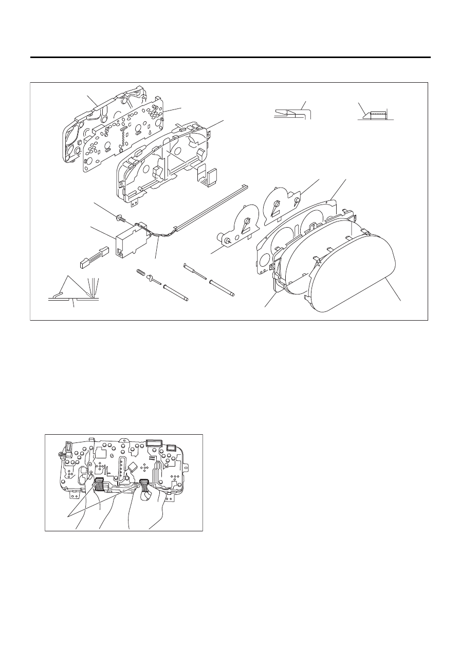
COMBINATION METER ASSEMBLY
2. LUMINESCENT METER
1) Remove screw (K) and disconnect connectors,
detach CFL (Cold Cathode Fluorescent Light) in-
verter (J).
2) Unfasten CFL harness (I) from back cover
groove.
3) Disengage claw (M) to remove meter glass (F),
reflector (G), and window plate (E) from case (C).
4) Remove connector cover and release connector
lock by pulling both end of it, disconnect FPC (Flex-
ible Printed Circuit) connector (P).
5) Pull up claw (N) on back cover (A) with combina-
tion pliers.
6) Push out speedometer assembly (H) and ta-
chometer assembly (D) using hole (O).
7) Disengage claw (L) to remove case (C) from
back cover (A).
8) Pull up claw in center of printed circuit (B), re-
move printed circuit from case (C).
IDI00049
( A )
( B )
( C )
( D )
( E )
( F )
( G )
( H )
( I )
( J )
( K )
( L )
( M )
( N )
( O )
IDI00050
( P )