Subaru Legacy III (2000-2003 year). Manual - part 905
AB-46
AIRBAG SYSTEM (DIAGNOSTICS)
DIAGNOSTIC CHART WITH DIAGNOSTIC TROUBLE CODE (DTC)
I:
DTC 25
DIAGNOSIS:
• Airbag control module is faulty.
• Airbag main harness circuit is open.
• Fuse No. 6 (in joint box) is blown.
• Body harness circuit is open.
CAUTION:
• Before diagnosing the airbag system, be sure to turn the ignition switch OFF, disconnect the
ground cable from the battery, and wait more than 20 seconds before starting to work.
• Before replacing the airbag module, roll connector, control module, and sensor, reconnect each
part and confirm that the warning light operates properly.
• When inspecting the airbag main harness, disconnect the driver's airbag module and passenger's
airbag module connectors for safety reasons.
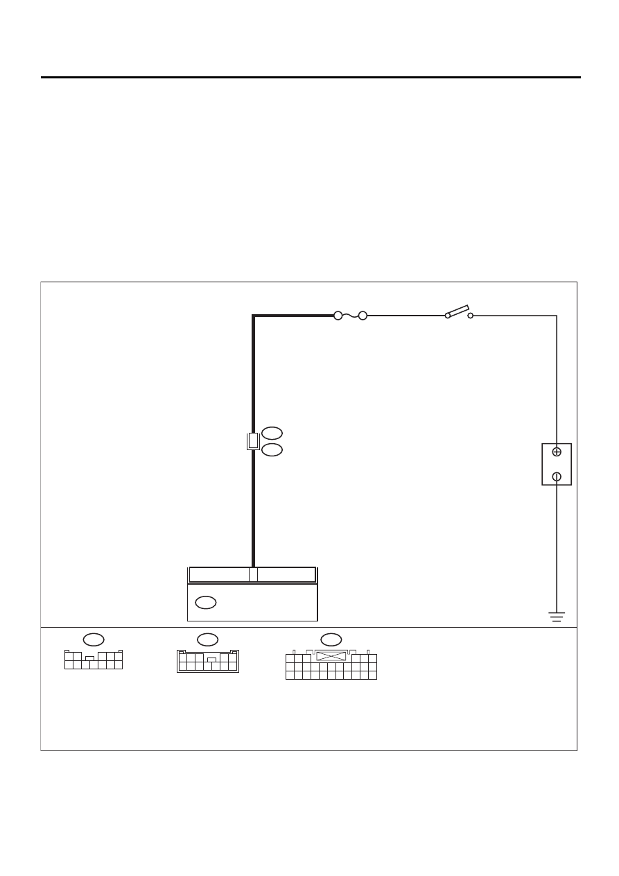
WIRING DIAGRAM:
AB-00296
5
11
AIRBAG CONTROL MODULE
AB6
B31
AB1
NO. 6
B
A
TTER
Y
IG SW
AB6
1 2 3
4 5 6
7 8 9 10 11 12 13 14 15 16 17
18 19 20 21 22 23 24 25 26 27 28
B31
1 2
3 4 5
6 7 8 9 10 11 12
AB1
1
2
3
4
5
6
7
8
9
10
11
12