Subaru Legacy III (2000-2003 year). Manual - part 836


  Index      Subaru     Subaru Legacy III - service repair manual 2000-2003 year


Search            


Content   ..  834  835  836  837   ..


Subaru Legacy III (2000-2003 year). Manual - part 836


PS-32

POWER ASSISTED SYSTEM (POWER STEERING)

STEERING GEARBOX [LHD MODEL]

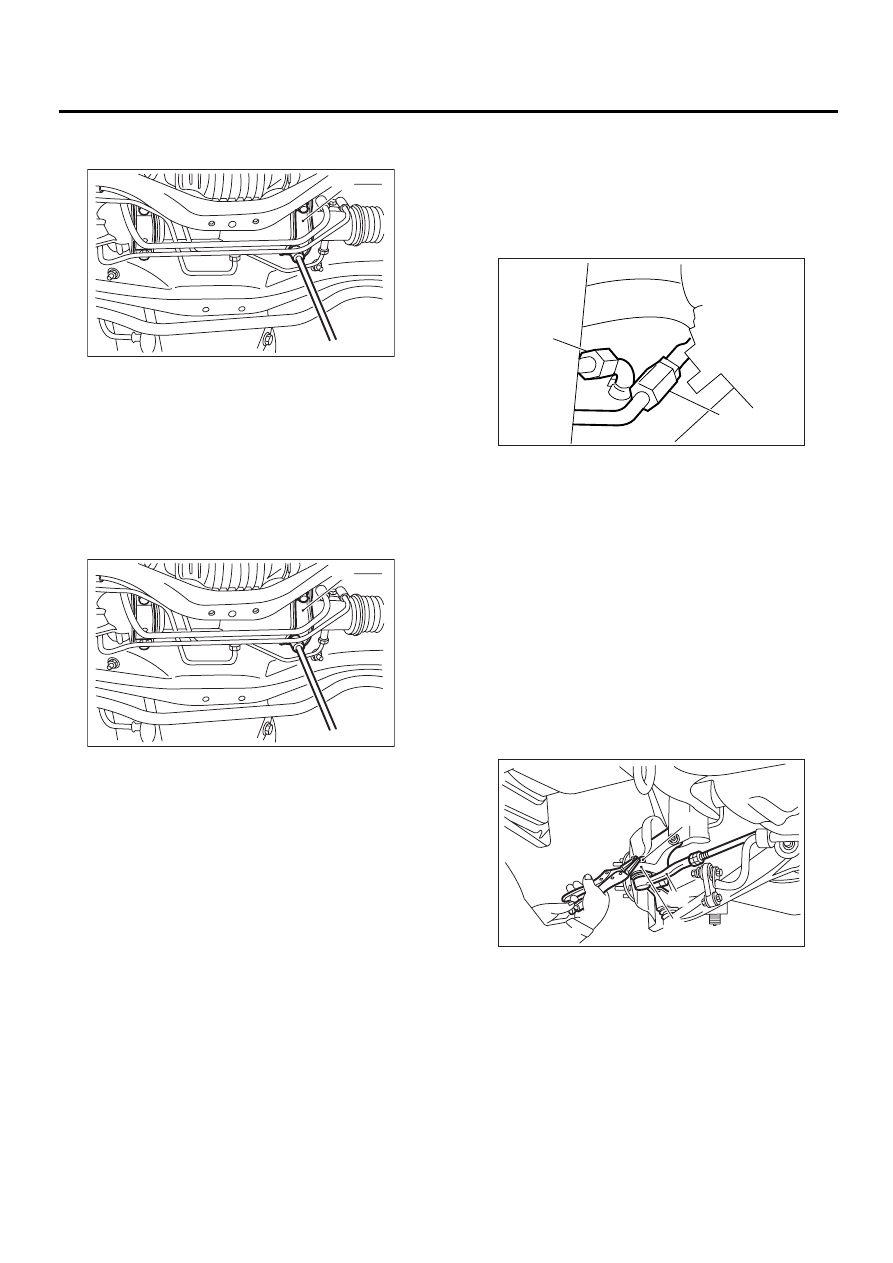
10) Remove clamp bolts securing gearbox to
crossmember, and remove gearbox.

B: INSTALLATION

1) Insert gearbox into crossmember, being careful
not to damage gearbox boot.
2) Tighten gearbox to crossmember bracket via
clamp with bolt to the specified torque.

Tightening torque:

59 N·m (6.0 kgf-m, 43 ft-lb)

3) Connect pipes C and D to pipe of gearbox.

NOTE:
Connect lower pipe C first, and upper pipe D sec-
ond.

CAUTION:
Be careful not to damage these pipes.

4) Install universal joint. <Ref. to PS-25, INSTAL-
LATION, Universal Joint.>
5) Connect tie-rod end and knuckle arm, and tight-
en with castle nut. Fit cotter pin into the nut and
bend the pin to lock.

Castle nut tightening torque:

Tighten to 27.0 N·m (2.75 kgf-m, 19.9 ft-lb), 
and tighten further within 60

°°°°

 until cotter 

pin hole is aligned with a slot in the nut.

CAUTION:
When connecting, do not hit cap at the bottom 
of tie-rod end with hammer.

6) Install front stabilizer to vehicle.  <Ref. to FS-21,
INSTALLATION, Front Stabilizer.>

(1) Clamp

(1) Clamp

PS-00028

( 1 )

PS-00028

( 1 )

(1) Pipe C

(2) Pipe D

(1) Castle nut

(2) Tie-rod end

(3) Knuckle arm

( 1 )

( 2 )

PS-00205

PS-00043

( 1 )

( 2 )

( 3 )

PS-33

POWER ASSISTED SYSTEM (POWER STEERING)

STEERING GEARBOX [LHD MODEL]

7) Install front exhaust pipe assembly.  <Ref. to
EX(H4SO)-6, INSTALLATION, Front Exhaust
Pipe.>

2.5 L model

<Ref. to EX(H4SO)-6, INSTALLATION, 
Front Exhaust Pipe.>

3.0 L model

<Ref. to EX(H6DO)-6, INSTALLATION, 
Front Exhaust Pipe.>

Turbo model

<Ref. to EX(H4DOSTC)-5, INSTALLATION, 
Front Exhaust Pipe.>

8) Install tires.
9) Tighten wheel nuts to the specified torque.

Tightening torque:

88 N·m (9.0 kgf-m, 65 ft-lb)

10) Connect battery ground cable.
11) Pour fluid into oil tank, and bleed air. 
<Ref. to PS-92, Power Steering Fluid.>
12) Check for fluid leaks. <Ref. to PS-49, OIL
LEAKING, INSPECTION, Steering Gearbox [LHD
MODEL].>
13) Install jack-up plate.
14) Lower vehicle.
15) Check fluid level in oil tank.
16) After adjusting toe-in and steering angle, tight-
en lock nut on tie-rod end.

Tightening torque:

83 N·m (8.5 kgf-m, 61.5 ft-lb)

CAUTION:
When adjusting toe-in, hold boot as shown to 
prevent it from being rotated or twisted. If twist-
ed, straighten it.

C: DISASSEMBLY

1. RACK HOUSING ASSEMBLY

1) Disconnect four pipes from gearbox.
2) Secure gearbox removed from vehicle in vise
using ST.
ST

926200000

 STAND

CAUTION:
Secure the gearbox in a vise using the ST as 
shown. Do not attempt to secure it without this 
ST.

3) Remove tie-rod end and lock nut from gearbox.
4) Remove small clip from boot using pliers, and
move boot to tie-rod end side.

5) Using standard screwdriver, remove band from
boot.

PS-00051

(1) Clip

(1) Band

(2) Standard screwdriver

PS-00029

ST

PS-00048

( 1 )

PS-00279

( 1 )

( 2 )

PS-34

POWER ASSISTED SYSTEM (POWER STEERING)

STEERING GEARBOX [LHD MODEL]

6) Extend rack approximately 40 mm (1.57 in) out.
Unlock lock wire at lock washer on each side of tie-
rod end using a standard screwdriver.

CAUTION:
Be careful not to scratch rack surface as oil 
leaks may result.

7) Using ST, loosen lock nut.
ST

926230000

SPANNER

8) Tighten adjusting screw until it no longer tight-
ens.

9) Using a wrench [32 mm (1.26 in) width across
flats] or adjustable wrench, remove tie-rod.

CAUTION:
• Check ball joint for free play, and tie-rod for
bends. Replace if necessary.

• Check dust seals used with tie-rod end ball
joint for damage or deterioration. Replace if
necessary.

10) Loosen adjusting screw and remove spring and
sleeve.

CAUTION:
Replace spring and/or sleeve if damaged.

11) Remove two bolts securing valve assembly.

12) Carefully draw out input shaft and remove
valve assembly.

(1) Standard screwdriver

(2) Lock washer

PS-00207

40 mm (1.57 in)

( 1 )

( 2 )

PS-00089

ST

PS-00109

PS-00110

PS-00109

PS-00116

PS-00117

PS-35

POWER ASSISTED SYSTEM (POWER STEERING)

STEERING GEARBOX [LHD MODEL]

13) Using a sharp pointed pliers, rotate the rack
stopper in the direction of the arrow until the end of
the circlip comes out of the stopper. Rotate the cir-
clip in the opposite direction and pull it out. 

14) Pull rack assembly from cylinder side, and
draw out rack bushing and rack stopper together
with rack assembly.

CAUTION:
Be careful not to contact rack to inner wall of 
cylinder when drawing out. Any scratch on cyl-
inder inner wall will cause oil leakage.

15) Remove rack bushing and rack stopper from
rack assembly.

CAUTION:
Do not reuse removed rack bushing and circlip.

16) Insert ST from pinion housing side and remove
oil seal using a press.
ST

34199AE050

OIL SEAL REMOVER

NOTE:
Discard removed oil seal.

2. CONTROL VALVE ASSEMBLY

NOTE:
Parts requiring replacement are described in the
smallest unit of spare parts including damaged
parts and spare parts damaged. In actual disas-
sembly work, accidental damage as well as inevita-
ble damage to some related parts must be taken
into account, and spare parts for them must also be
prepared. However, it is essential to pinpoint the
cause of trouble, and limit the number of replace-
ment parts as much as possible.
1) Using ST, loosen lock nut.
ST

926230000

SPANNER

(1) Rack bushing

(2) Rack ASSY

(3) Rack stopper

PS-00121

PS-00132

( 1 )

( 2 )

( 3 )

(1) Press

(2) Oil seal

PS-00138

ST

( 1 )

( 2 )

PS-00089

ST


Content   ..  834  835  836  837   ..