Subaru Legacy III (2000-2003 year). Manual - part 737
VDC-16
VDC
ABS SEQUENCE CONTROL
4. ABS Sequence Control
A: OPERATION
1) Under the ABS sequence control, after the hy-
draulic unit solenoid valve is driven, the operation
of the hydraulic unit can be checked by means of
the brake tester or pressure gauge.
2) ABS sequence control can be started by diagno-
sis connector or select monitor.
1. ABS SEQUENCE CONTROL WITH DIAG-
NOSIS CONNECTOR
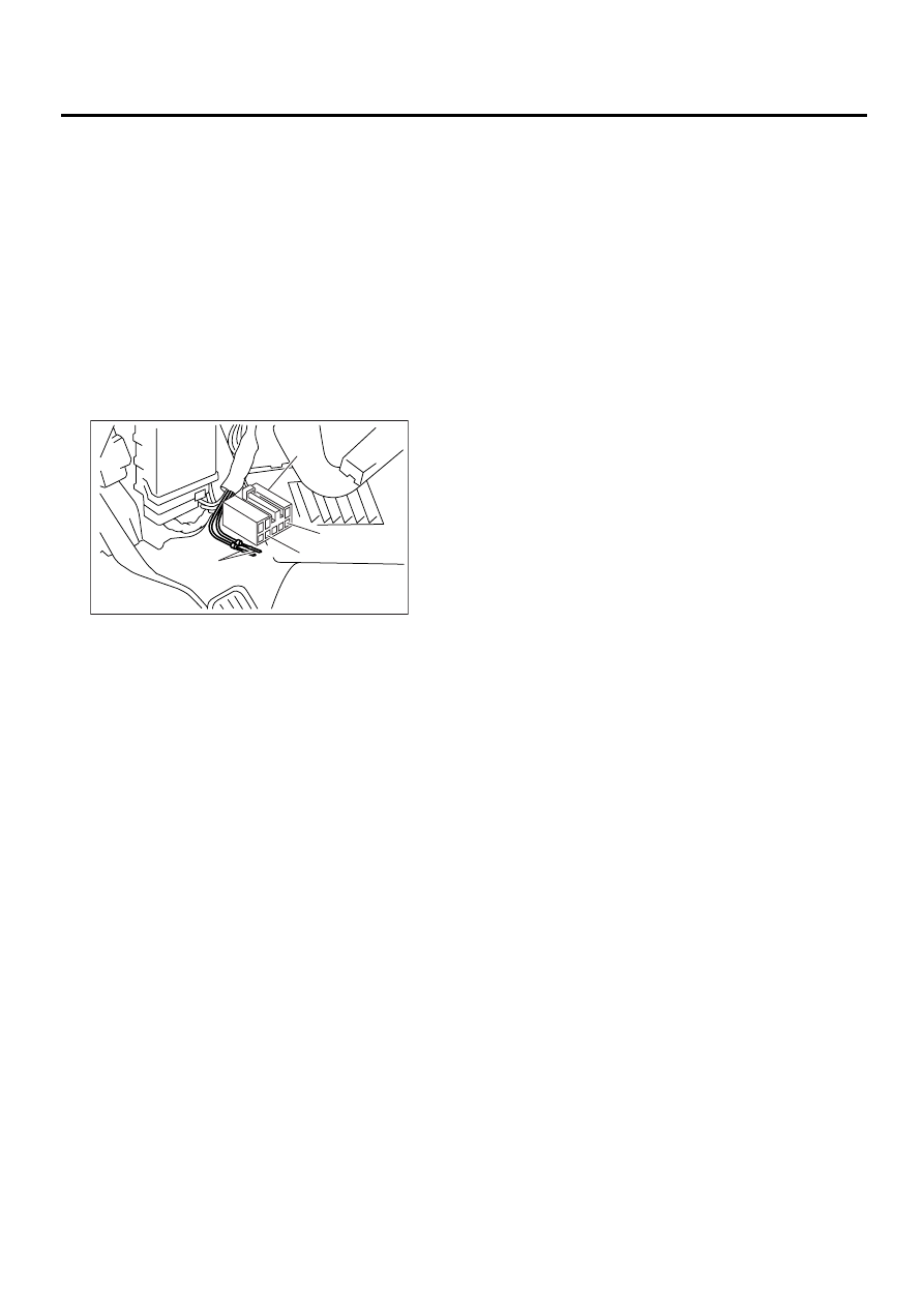
1) Connect diagnosis terminals to terminals No. 5
and No. 8 of the diagnosis connector beside driv-
er's seat heater unit.
2) Set the speed of all wheels at 2.75 km/h (2 MPH)
or less.
3) Turn ignition switch OFF.
4) Within 0.5 seconds after the ABS and VDC
warning light goes out, depress the brake pedal
and hold it immediately after ignition switch is
turned to ON.
CAUTION:
Do not depress the clutch pedal.
NOTE:
• When the ignition switch is set to on, the brake
pedal must not be depressed.
• Engine must not operate.
5) After completion of ABS sequence control, turn
ignition switch OFF.
2. ABS SEQUENCE CONTROL WITH SE-
LECT MONITOR
NOTE:
• In the event of any trouble, the sequence control
may not be operative. In such a case, activate the
sequence control, referring to “ABS SEQUENCE
CONTROL WITH DIAGNOSIS CONNECTOR”.
<Ref. to VDC-16, ABS SEQUENCE CONTROL
WITH DIAGNOSIS CONNECTOR, OPERATION,
ABS Sequence Control.>
• When the diagnosis terminal is connected to the
diagnosis connector, the sequence control will not
operate.
1) Connect select monitor to data link connector
beside driver's seat instrument panel lower cover.
2) Turn ignition switch ON.
3) Turn select monitor switch ON.
4) Put select monitor to “BRAKE CONTROL”
mode.
5) When “Function check sequence” is selected,
`ABS sequence control' will start.
6) The message `Press Brake Pedal Firmly' is dis-
played as follows:
(1) When using the brake tester, depress brake
pedal with braking force of 981 N (100 kgf, 221
lb).
(2) When using the pressure gauge, depress
brake pedal so as to make the pressure gauge
indicate 3,432 kPa (35 kg/cm
2
, 498 psi).
CAUTION:
Do not depress the clutch pedal.
7) When the message “Press YES” is displayed,
press «YES» key.
8) Operation points will be displayed on select
monitor.
(1) Diagnosis connector
(2) Diagnosis terminal
(3) 8 terminal
(4) 5 terminal
( 1 )
( 2 )
( 3 )
( 4 )
ABS00159