Subaru Legacy III (2000-2003 year). Manual - part 728
ABS-130
ABS (DIAGNOSTICS)
DIAGNOSTICS CHART WITH SUBARU SELECT MONITOR
AC:DTC 52 MOTOR MALFUNCTION
DIAGNOSIS:
• Faulty motor
• Faulty motor relay
• Faulty harness connector
TROUBLE SYMPTOM:
• ABS does not operate.
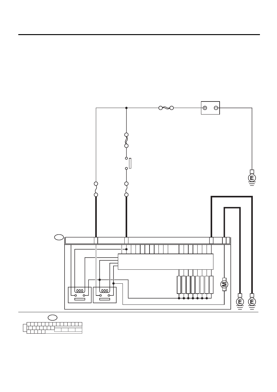
WIRING DIAGRAM:
ABS00298
ABS CONTROL MODULE AND
HYDRAULIC CONTROL UNIT
1 2 3 4 5 6 7 8 9 10 11 12 13 14 15
16 17 18 19 20 21 22
27 28 29 30 31
23
24
25
26
F49
25
1
23
26
VALVE RELAY
F49
MOTOR RELAY
FR OUTLET
FR INLET
RL OUTLET
RL INLET
RR OUTLET
RR INLET
FL OUTLET
FL INLET
SOLENOID
VA
L
V
E
PUMP MO
T
O
R
SBF HOLDER 50A
NO
. 10 15A
SBF-4 50A
IGNITION
SWITCH
SBF-1 100A
BATTERY