Subaru Legacy III (2000-2003 year). Manual - part 724
ABS-114
ABS (DIAGNOSTICS)
DIAGNOSTICS CHART WITH SUBARU SELECT MONITOR
U: DTC 42 POWER SUPPLY VOLTAGE TOO LOW
DIAGNOSIS:
• Power source voltage of the ABSCM&H/U is low.
TROUBLE SYMPTOM:
• ABS does not operate.
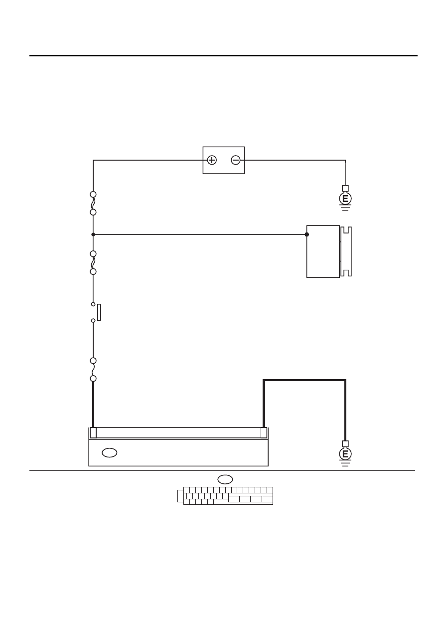
WIRING DIAGRAM:
ABS00294
1
23
ABS CONTROL MODULE AND HYDRAULIC CONTROL UNIT
F49
1 2 3 4 5 6 7 8 9 10 11 12 13 14 15
16 17 18 19 20 21 22
27 28 29 30 31
23
24
25
26
F49
BATTERY
NO
. 18 15A
SBF-4 50A
SBF-1 100A
GENERATOR
IGNITION
SWITCH