Subaru Legacy III (2000-2003 year). Manual - part 687


  Index      Subaru     Subaru Legacy III - service repair manual 2000-2003 year


Search            


Content   ..  685  686  687  688   ..


Subaru Legacy III (2000-2003 year). Manual - part 687


DS-26

DRIVE SHAFT SYSTEM

HUB UNIT BEARING

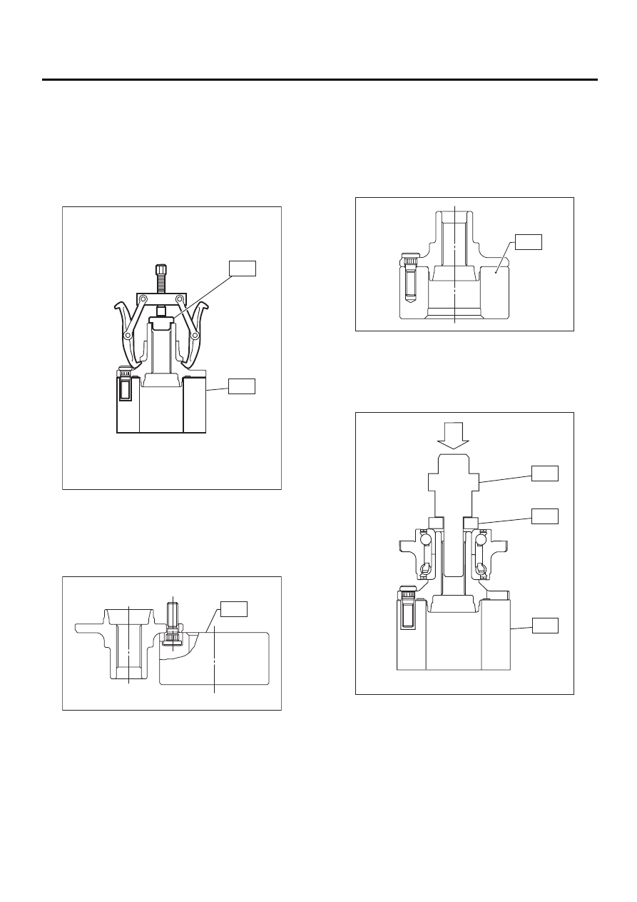
2) Using ST and a puller (common hand tool), re-
move bearing inner race.
ST1

399520105

SEAT

ST2

927080000

HUB STAND

CAUTION:
• Do not remove hub unit bearing unless dam-
aged.
• Do not re-use hub unit bearing after removal.

3) Using ST, press hub bolt out.
ST

927080000

HUB STAND

CAUTION:
Be careful not to hammer hub bolts. This may 
deform hub.

D: ASSEMBLY

1) Using ST, press new hub bolt into place.

CAUTION:
• Ensure hub bolt closely contacts hub.
• Use a 12 mm (0.47 in) hole in the ST to pre-
vent hub bolt from tilting during installation.
ST

927080000

HUB STAND

2) Using ST1, ST2 and ST3, press hub unit bearing
into hub.
ST1

927080000

HUB STAND

ST2

927450000

HUB INSTALLER

ST3

28499AE000 SPACER

CAUTION:
• Always press inner race when installing hub
unit bearing.
• Use a new hub unit bearing.

ST1

ST2

DS-00155

DS-00054

ST

DS-00055

ST

ST1

ST2

ST3

DS-00156

DS-27

DRIVE SHAFT SYSTEM

HUB UNIT BEARING

E: INSPECTION

Check the removed parts for wear and damage. If
defective, replace with new ones.

CAUTION:
If a bearing is faulty, replace it as a hub unit 
bearing.

DS-28

DRIVE SHAFT SYSTEM

FRONT DRIVE SHAFT

5. Front Drive Shaft

A: REMOVAL

1) Disconnect ground cable from battery.
2) Jack-up vehicle, support it with safety stands
(rigid rocks), and remove front wheel cap and
wheels.
3) Unlock axle nut.
4) Depress brake pedal and remove axle nut using
a socket wrench.

CAUTION:
Be sure to loosen and retighten axle nut after 
removing wheel from vehicle. Failure to follow 
this rule may damage wheel bearings.
5) Remove stabilizer link from transverse link.
6) Disconnect transverse link from housing.
7) Remove spring pin which secures transmission
spindle to SFJ.

CAUTION:
Use a new spring pin.

8) Remove front drive shaft assembly. If it is hard to
remove, use ST1 and ST2.
ST1

926470000

AXLE SHAFT PULLER

ST2

927140000

PLATE

CAUTION:
• Be careful not to damage oil seal lip and tone
wheel when removing front drive shaft.
• When front drive shaft is to be replaced, also
replace inner oil seal.

B: INSTALLATION

1) Insert BJ into hub splines.

CAUTION:
Be careful not to damage inner oil seal lip and 
tone wheel.
2) Using ST1 and ST2, pull drive shaft into place.
ST1

922431000

AXLE SHAFT INSTALLER

ST2

927390000

ADAPTER

CAUTION:
Do not hammer drive shaft when installing it.

3) Tighten axle nut temporarily.
4) Install SFJ on transmission spindle and drive
spring pin into place.

CAUTION:
Always use a new spring pin.

5) Connect transverse link to housing.

Tightening torque (self-locking nut):

49 N·m (5.0 kgf-m, 36 ft-lb)

CAUTION:
Use a new self-locking nut.
6) Install stabilizer bracket.

DS-00157

DS-00145

ST2

ST1

DS-00104

ST

DS-00157

DS-29

DRIVE SHAFT SYSTEM

FRONT DRIVE SHAFT

7) While depressing brake pedal, tighten axle nut to
the specified torque.

Tightening torque:

216 N·m (22 kgf-m, 159 ft-lb)

CAUTION:
• Use a new axle nut (Olive color).
• Always tighten axle nut before installing
wheel on vehicle. If wheel is installed and
comes in contact with ground when axle nut is
loose, wheel bearings may be damaged.
• Be sure to tighten axle nut to specified
torque. Do not overtighten it as this may dam-
age wheel bearing.
8) After tightening axle nut, lock it securely.

C: DISASSEMBLY

1) Place alignment marks on shaft and outer race.

2) Remove SFJ boot band and boot.

CAUTION:
Be careful not to damage boot.

3) Remove circlip from SFJ outer race using screw-
driver.

4) Remove SFJ outer race from shaft assembly.
5) Wipe off grease.

CAUTION:
The grease is a special grease. Do not confuse 
with other greases.
6) Place alignment mark on free ring and trunnion.

7) Remove free ring from trunnion.

CAUTION:
Be careful with the free ring position.
8) Place alignment mark on trunnion and shaft.

DS-00158

DS-00159

DS-00160

DS-00109

DS-00110


Content   ..  685  686  687  688   ..