Subaru Legacy III (2000-2003 year). Manual - part 672


  Index      Subaru     Subaru Legacy III - service repair manual 2000-2003 year


Search            


Content   ..  670  671  672  673   ..


Subaru Legacy III (2000-2003 year). Manual - part 672


DI-42

DIFFERENTIALS

REAR DIFFERENTIAL FOR VA-TYPE

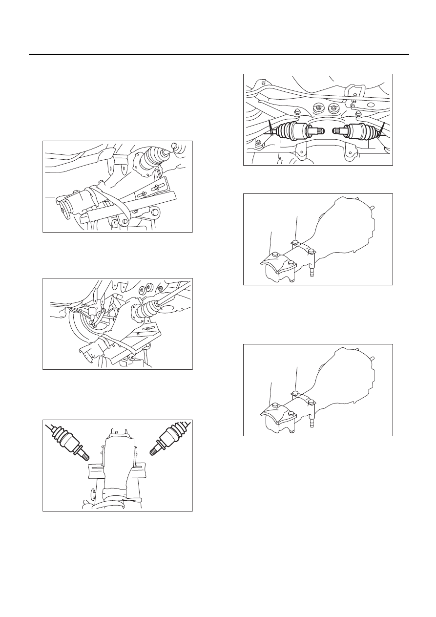
18) Remove self-locking nuts connecting rear dif-
ferential to rear crossmember.
19) Remove rear differential stud bolt from rear
crossmember bushing.

NOTE:
Carefully adjust angle and position of transmission
jack and jack stand as required during stud bolt re-
moval.

20) After removing rear differential stud bolt from
rear crossmember, lower transmission jack stand.
Do not allow rear drive shaft to strike lateral link
bolt.

21) Pull out axle shaft from rear differential.

NOTE:
If axle shaft is difficult to remove from rear differen-
tial, use a tire lever to remove it.

22) Take down transmission jack.

23) Secure rear drive shaft to lateral link using wire.

24) Remove protector and rear differential member
plate from rear differential.

B: INSTALLATION

1) Insert protector and plate to rear differential.

2) Set rear differential to transmission jack.

NOTE:
Secure rear differential to transmission jack using a
band.

DI-00274

DI-00275

DI-00276

(A) Protector

(B) Rear differential member plate

(A) Protector

(B) Rear differential member plate

DI-00277

DI-00278

( A )

( B )

DI-00278

( A )

( B )

DI-43

DIFFERENTIALS

REAR DIFFERENTIAL FOR VA-TYPE

3) Install ST to rear differential.
ST

28099PA090

OIL SEAL PROTECTOR

4) Insert the spline shaft until the spline portion is
inside the side oil seal.

5) Remove ST from rear differential.
ST

28099PA090

OIL SEAL PROTECTOR

6) Completely insert axle shaft into rear differential
by pressing rear differential.

7) Adjust transmission jack as required so rear dif-
ferential stud bolt is properly inserted into rear
crossmember bushing.

8) After rear differential stud bolt has been inserted
into rear crossmember bushing, raise transmission
jack to make jack rear differential level.

9) Temporarily tighten rear crossmember self-lock-
ing nuts.

10) Remove band from rear differential. Raise rear
differential just enough to move transmission jack
away from it.
11) Install rear differential front member.

Tightening torque:

T1: 65 N·m (6.6 kgf-m, 48 ft-lb)
T2: 110 N·m (11.2 kgf-m, 81 ft-lb)

DI-00300

ST

DI-00289

ST

DI-00281

DI-00282

DI-00283

DI-00269

DI-00284

T2

T1

DI-44

DIFFERENTIALS

REAR DIFFERENTIAL FOR VA-TYPE

12) Tighten self-locking nuts.

Tightening torque:

70 N·m (7.1 kgf-m, 51 ft-lb)

13) Tighten protector nut.

Tightening torque:

65 N·m (6.6 kgf-m, 48.0 ft-lb)

14) Take down transmission jack.
15) Install propeller shaft.
<Ref. to DS-15, INSTALLATION, Propeller Shaft.>
16) Install heat shield cover.
17) Install rear exhaust pipe and muffler.

C: DISASSEMBLY

To detect real cause of trouble, inspect the follow-
ing items before disassembling.
• Tooth contact of crown gear and pinion, and
backlash
• Runout of crown gear at its back surface
• Turning resistance of drive pinion
1) Set ST on vise and install the differential assem-
bly to ST.
ST

398217700

ATTACHMENT

2) Drain gear oil by removing plug.
3) Remove rear cover by loosening retaining bolts.

4) Replace air breather cap.

NOTE:
Do not attempt to replace the air breather cap un-
less necessary.

5) Remove right and left lock plates.

DI-00269

DI-00272

DI-00129

ST

(A) Air breather cap

(B) Rear cover

DI-00130

DI-00131

( A )

( B )

DI-00132

DI-45

DIFFERENTIALS

REAR DIFFERENTIAL FOR VA-TYPE

6) Remove right and left holders with ST.
ST

399780111

WRENCH

7) Pull out differential assembly from differential
case.

NOTE:
Be careful not to hit the teeth against the case.

8) Remove bearing race from right and left holders
with ST1 and ST2.
ST1

499705401

BEARING OUTER RACE 
PULLER ASSY

ST2

499705404

OUTER RACE PULLER 
SEAT

9) Remove oil seal from right and left holders with
screwdriver.

10) Extract bearing cone with ST1 and ST2.

NOTE:
• Do not attempt to disassemble the parts unless
necessary.
• Set puller so that its claws catch the edge of the
bearing cone.
• Never mix up the right and left hand bearing rac-
es and cones.
ST1

899524100

PULLER SET

ST2

399520105

SEAT

11) Remove crown gear by loosening crown gear
bolts.

(A) Bearing race

(B) Holder

DI-00133

ST

DI-00134

DI-00135

( A )

( B )

ST1

ST2

DI-00136

DI-00137

ST2

ST1

DI-00068


Content   ..  670  671  672  673   ..