Subaru Legacy III (2000-2003 year). Manual - part 593


  Index      Subaru     Subaru Legacy III - service repair manual 2000-2003 year


Search            


Content   ..  591  592  593  594   ..


Subaru Legacy III (2000-2003 year). Manual - part 593


AT-106

AUTOMATIC TRANSMISSION (DIAGNOSTICS)

DIAGNOSTIC PROCEDURE WITH DIAGNOSTIC TROUBLE CODE (DTC)

Q: DTC 79 TRANSFER DUTY SOLENOID

DIAGNOSIS:
Output signal circuit of transfer duty solenoid is open or shorted.
TROUBLE SYMPTOM:
Excessive “braking” in tight corners.
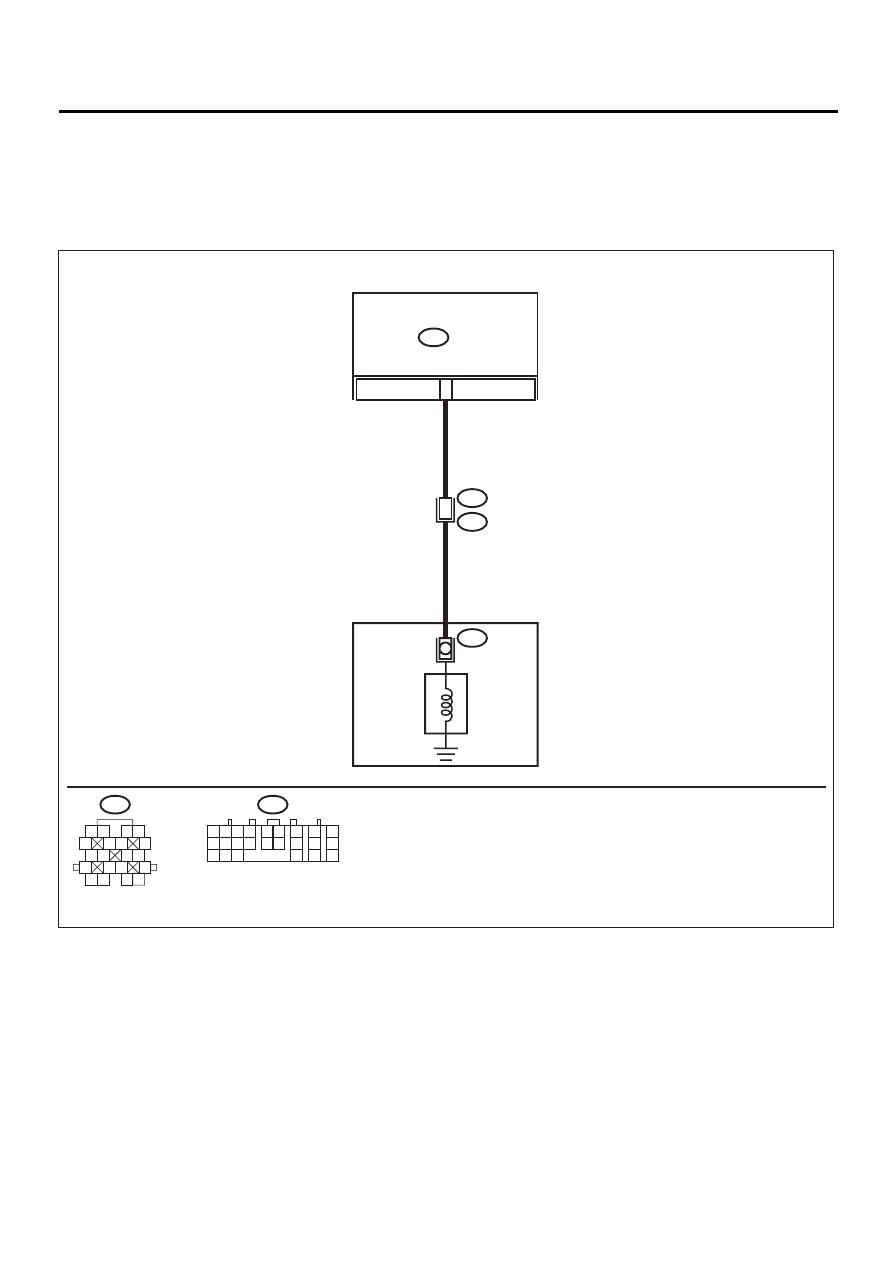
WIRING DIAGRAM:

AT-00590

-

6

TRANSMISSION

B54

TCM

AT4

6

T4

B11

TRANSFER

DUTY

SOLENOID

B54

1 2

7

8

9

5 6

3 4

10 11 12
19 20 21

13

14 15

16

17

18

22

23

24

B11

1 2

5

6 7

8

13

14 15

16

9 10

11 12

3 4

17 18

19 20

AT-107

AUTOMATIC TRANSMISSION (DIAGNOSTICS)

DIAGNOSTIC PROCEDURE WITH DIAGNOSTIC TROUBLE CODE (DTC)

Step

Value

Yes

No

1

CHECK HARNESS CONNECTOR BETWEEN 
TCM AND TRANSMISSION.
1) Turn ignition switch to OFF.
2) Disconnect connector from TCM and trans-

mission.

3) Measure resistance of harness between 

TCM and transmission connector.

Connector & terminal

(B54) No. 6 — (B11) No. 6:

Is the measured value less than the speci-
fied value?

Go to step 2.

Repair open circuit 
in harness 
between TCM and 
transmission con-
nector.

2

CHECK HARNESS CONNECTOR BETWEEN 
TCM AND TRANSMISSION.
Measure resistance harness connector 
between TCM and chassis ground.

Connector & terminal

(B54) No. 6 — Chassis ground:

Does the measured value exceed the specified 
value?

1 M

Go to step 3.

Repair short circuit 
in harness 
between TCM and 
transmission con-
nector.

3

CHECK TRANSFER DUTY SOLENOID.
Measure resistance between transmission 
connector and transmission terminals.

Connector & terminal

(T4) No. 6 — No. 16:

Is the measured value within the specified 
range?

10 — 17 

Go to step 4.

Go to step 13.

4

PREPARE SUBARU SELECT MONITOR.
Do you have a Subaru Select Monitor?

Subaru Select Monitor is avail-
able.

Go to step 7.

Go to step 5.

5

CHECK OUTPUT SIGNAL EMITTED FROM 
TCM.
1) Connect connectors to TCM and transmis-

sion.

2) Turn ignition switch to ON (engine OFF).
3) Select lever is moved to P range.
4) Throttle is fully closed.
5) Measure voltage between TCM connector 

and chassis ground.

Connector & terminal

(B54) No. 6 (+) — Chassis ground (

−−−−

):

Is the measured value less than the speci-
fied value?

1 V

Go to step 9.

Go to step 12.

6

CHECK OUTPUT SIGNAL EMITTED FROM 
TCM.
1) Select lever is moved to D range.
2) Measure voltage between TCM connector 

and chassis ground.

Connector & terminal

(B54) No. 6 (+) — Chassis ground (

−−−−

):

Is the measured value within the specified 
range?

5 — 7 V

Even if “POWER” 
indicator lights up, 
the circuit has 
returned to a nor-
mal condition at 
this time. A tempo-
rary poor contact 
of the connector or 
harness may be 
the cause. Repair 
harness or con-
nector in the trans-
fer duty solenoid 
and TCM connec-
tor.

Go to step 12.

7

CHECK SPECIFICATIONS.
Is VDC system or SPORT shift equipped?

The vehicle is equipped with 
the VDC system or SPORT 
shift.

Go to step 10.

Go to step 8.

AT-108

AUTOMATIC TRANSMISSION (DIAGNOSTICS)

DIAGNOSTIC PROCEDURE WITH DIAGNOSTIC TROUBLE CODE (DTC)

8

CHECK OUTPUT SIGNAL EMITTED FROM 
TCM USING SUBARU SELECT MONITOR.
1) Connect connectors to TCM and transmis-

sion.

2) Connect Subaru Select Monitor to data link 

connector.

3) Turn ignition switch to ON (engine OFF) 

and turn Subaru Select Monitor switch to 
ON.

4) Shift select lever to D and open throttle fully 

(vehicle speed 0 km/h or 0 MPH).

5) Read data of transfer duty solenoid using 

Subaru Select Monitor.

•Transfer duty solenoid is indicated in “%”.

Is transfer duty solenoid data within the 
specified range?

5 — 10%

Go to step 9.

Go to step 12.

9

CHECK OUTPUT SIGNAL EMITTED FROM 
TCM USING SUBARU SELECT MONITOR.
1) Move select lever to “N” with throttle fully 

closed (vehicle speed 0 km/h or 0 MPH).

2) Read data of transfer duty solenoid using 

Subaru Select Monitor.

•Transfer duty solenoid is indicated in “%”.

Is transfer duty solenoid data within the 
specified range?

Approx. 60 — 70%

Even if “POWER” 
indicator lights up, 
the circuit has 
returned to a nor-
mal condition at 
this time. A tempo-
rary poor contact 
of the connector or 
harness may be 
the cause. Repair 
harness or con-
nector in the trans-
fer duty solenoid 
and TCM connec-
tor.

Go to step 12.

10

CHECK OUTPUT SIGNAL EMITTED FROM 
TCM USING SUBARU SELECT MONITOR.
1) Connect connectors to TCM and transmis-

sion.

2) Connect Subaru Select Monitor to data link 

connector.

3) Turn ignition switch to ON (engine OFF) 

and turn Subaru Select Monitor switch to 
ON.

4) Shift select lever to D and open throttle fully 

(vehicle speed 0 km/h or 0 MPH).

5) Read data of transfer duty solenoid using 

Subaru Select Monitor.

•Transfer duty solenoid is indicated in “%”.

Is transfer duty solenoid data within the 
specified range?

80 — 95%

Go to step 11.

Go to step 12.

Step

Value

Yes

No

AT-109

AUTOMATIC TRANSMISSION (DIAGNOSTICS)

DIAGNOSTIC PROCEDURE WITH DIAGNOSTIC TROUBLE CODE (DTC)

11

CHECK OUTPUT SIGNAL EMITTED FROM 
TCM USING SUBARU SELECT MONITOR.
1) Move select lever to “N” with throttle fully 

close (vehicle speed 0 km/h or 0 MPH).

2) Rear data of transfer duty solenoid using 

Subaru Select Monitor.

•Transfer duty solenoid is indicated in “%”.

Is transfer duty solenoid data the specified 
value?

Approx. 40%

Even if “POWER” 
indicator lights up, 
the circuit has 
returned to a nor-
mal condition at 
this time. A tempo-
rary poor contact 
of the connector or 
harness may be 
the cause. Repair 
harness or con-
nector in the trans-
fer duty solenoid 
and TCM connec-
tor.

Go to step 12.

12

CHECK POOR CONTACT.
Is there poor contact in transfer duty solenoid 
circuit?

There is poor contact.

Repair poor con-
tact.

Replace TCM. 
<Ref. to AT-76, 
Transmission Con-
trol Module 
(TCM).>

13

CHECK TRANSFER DUTY SOLENOID (IN 
TRANSMISSION).
1) Lift-up the vehicle and place safety stand.
2) Drain automatic transmission fluid.

CAUTION:

Do not drain the automatic transmission flu-
id until it cools down.

3) Remove extension case, and disconnect 

connector from transfer duty solenoid.

4) Measure resistance between transfer duty 

solenoid connector and transmission 
ground.

Connector & terminal

(AT4) No. 1 — Transmission ground:

Is the measured value within the specified 
range?

10 — 17 

Go to step 14.

Replace transfer 
duty solenoid.

14

CHECK HARNESS CONNECTOR BETWEEN 
TRANSFER DUTY SOLENOID AND TRANS-
MISSION.
Measure resistance of harness between trans-
fer duty solenoid and transmission connector.

Connector & terminal

(T4) No. 6 — (AT4) No. 1:

Is the measured value less than the specified 
value?

Go to step 15.

Repair open circuit 
in harness 
between transfer 
duty solenoid and 
transmission con-
nector.

Step

Value

Yes

No


Content   ..  591  592  593  594   ..