Subaru Legacy III (2000-2003 year). Manual - part 578
AT-46
AUTOMATIC TRANSMISSION (DIAGNOSTICS)
DIAGNOSTIC PROCEDURE WITH DIAGNOSTIC TROUBLE CODE (DTC)
B: DTC 23 MASS AIR FLOW SIGNAL (TURBO MODEL)
DIAGNOSIS:
The input signal circuit of TCM from ECM is open or shorted.
TROUBLE SYMPTOM:
Excessive shift shock.
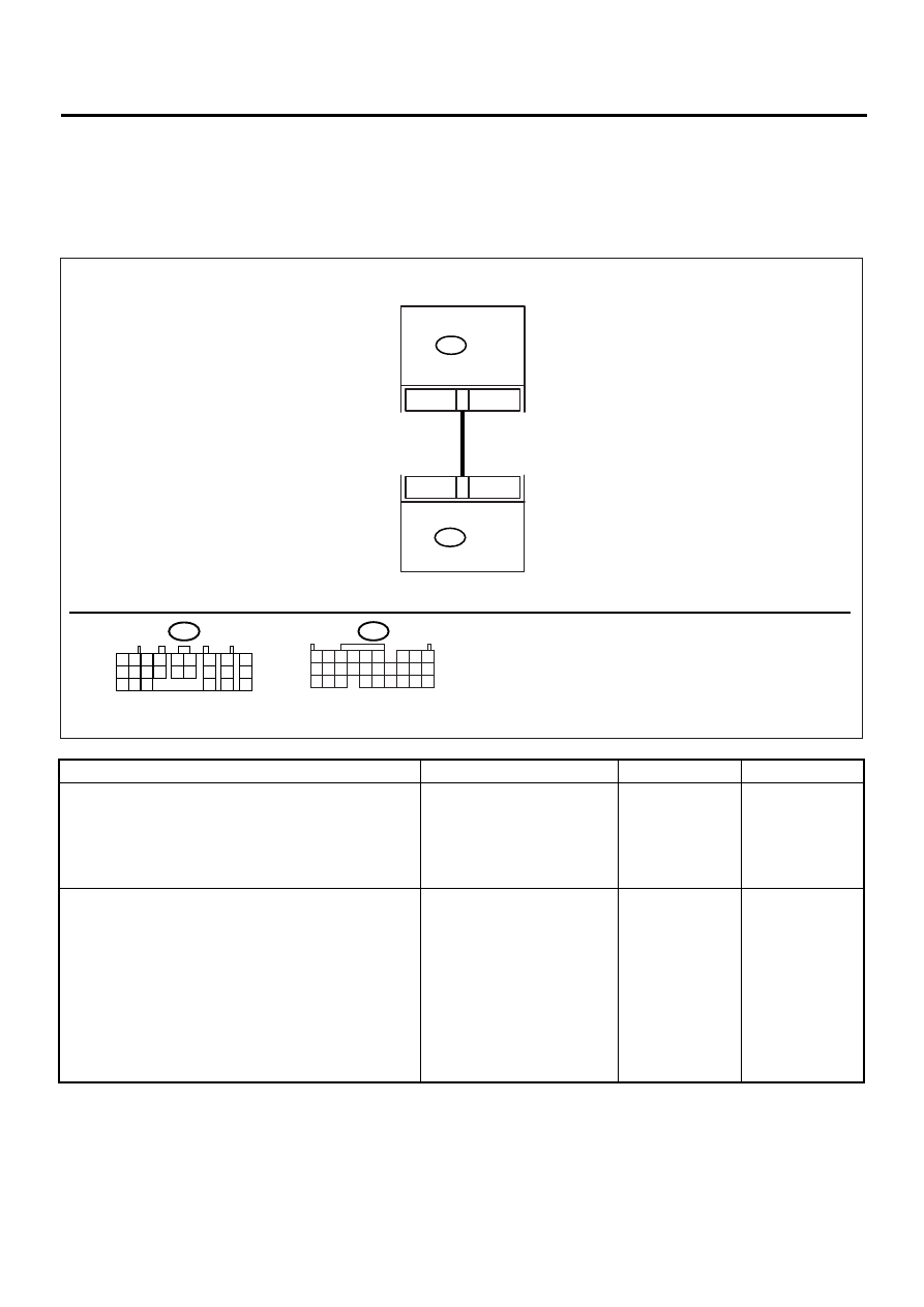
WIRING DIAGRAM:
Step
Value
Yes
No
1
CHECK ENGINE GROUND TERMINALS AND
GROUND CIRCUIT OF ECM.
<Ref. to AT-52, DTC 31 THROTTLE POSI-
TION SENSOR, Diagnostic Procedure with
Diagnostic Trouble Code (DTC).>
Is there any trouble?
There is a trouble.
Repair the ground
terminal and/or
ground circuit of
ECM.
2
CHECK HARNESS CONNECTOR BETWEEN
TCM AND ECM.
1) Turn the ignition switch to OFF.
2) Disconnect the connectors from TCM and
ECM.
3) Measure the resistance of harness
between TCM and ECM connector.
Connector & terminal
(B54) No. 1 — (B135) No. 28:
Is the measured value less than the speci-
fied value?
1
Ω
Repair the open
circuit in harness
between TCM and
ECM connector.
AT-00574
28
1
B54
B54
B135 ECM
TCM
1
2
3
4
5
6
7
8
9
10 11 12 13 14 15
16
17
18
19 20 21
22 23
24
B135
5 6
7 8
2
1
9
4
3
10
24
22
23
25
11 12 13 14 15
26 27 28
16 17 18 19
20 21