Subaru Legacy III (2000-2003 year). Manual - part 553


  Index      Subaru     Subaru Legacy III - service repair manual 2000-2003 year


Search            


Content   ..  551  552  553  554   ..


Subaru Legacy III (2000-2003 year). Manual - part 553


AT-106

AUTOMATIC TRANSMISSION

CENTER DIFFERENTIAL CARRIER

31.Center Differential Carrier

A: REMOVAL

1) Remove the transmission assembly from vehi-
cle. <Ref. to AT-39, REMOVAL, Automatic Trans-
mission Assembly.>
2) Remove the rear wheel speed sensor, and sep-
arate the extension case from the transmission
case. <Ref. to AT-86, REMOVAL, Extension
Case.>
3) Pull out the rear driveshaft. <Ref. to AT-99, RE-
MOVAL, Rear Drive Shaft.>
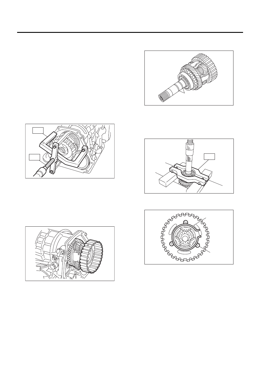
4) Using the special tools, pull out the center differ-
ential carrier assembly.
ST1

499737100

PULLER

ST2

899524100

PULLER SET

5) Pull out the shim(s) from transmission case.

B: INSTALLATION

1) Install the center differential assembly with the
shim(s).

NOTE:
Insert the center differential assembly and shim(s)
completely into the bearing shoulder bottom.

2) Insert the rear driveshaft. <Ref. to AT-99, IN-
STALLATION, Rear Drive Shaft.>
3) Connect the transmission case and extension
case, and install the rear wheel speed sensor.
<Ref. to AT-86, INSTALLATION, Extension Case.>
4) Install the transmission assembly onto vehicle.
<Ref. to AT-42, INSTALLATION, Automatic Trans-
mission Assembly.>

C: DISASSEMBLY

1) Remove the seal rings.

2) Using a press and the special tool, remove the
ball bearing.
ST

498077600

REMOVER

3) Remove the snap ring, and pull out the shaft
from the center differential assembly.

AT-00164

ST1

ST2

AT-00165

(A) Seal ring

(A) Snap ring

(B) Shaft

AT-00166

( A )

AT-00167

ST

( A )

( B )

AT-00168

AT-107

AUTOMATIC TRANSMISSION

CENTER DIFFERENTIAL CARRIER

4) Remove the thrust washers, pinion gears, and
washers from the center differential assembly. 

5) Pull out the intermediate shaft and thrust bear-
ing. 

D: ASSEMBLY

1) Install the thrust washer onto the intermediate
shaft.
2) Install thrust bearing onto the intermediate shaft.
3) Install the pinion gears and washers.
4) Insert the shaft into the center differential as-
sembly.
5) Install the snap ring. 
6) Using a press, install a new ball bearing into the
center differential assembly.
ST

498077000

REMOVER

7) Apply Vaseline onto the seal ring outer surface
and shaft grooves.
8) Install new seal rings.

E: INSPECTION

• Check all parts for hole, score, or dirt. 
• Check the play of the extension end, and if nec-
essary, adjust it. <Ref. to AT-95, VTD MODEL, AD-
JUSTMENT, Transfer Clutch.>

(A) Pinion gear

AT-00169

( A )

(A) Plate

(B) Center differential carrier

AT-00170

( A )

( B )

ST

AT-108

AUTOMATIC TRANSMISSION

PARKING PAWL

32.Parking Pawl

A: REMOVAL

1) Remove the transmission assembly from the ve-
hicle. <Ref. to AT-39, REMOVAL, Automatic
Transmission Assembly.>
2) Remove rear vehicle speed sensor and separate
transmission case and extension case sections.
<Ref. to AT-86, REMOVAL, Extension Case.>
3) Remove the reduction drive gear. (MPT model)
<Ref. to AT-104, REMOVAL, Reduction Drive
Gear.>
4) Remove the center differential carrier. (VTD
model) <Ref. to AT-106, REMOVAL, Center Differ-
ential Carrier.>
5) Remove the parking pawl, return spring and
shaft.

B: INSTALLATION

1) Install the parking pawl, shaft and return spring.

2) Install the reduction drive gear. <Ref. to AT-104,
INSTALLATION, Reduction Drive Gear.>
3) Install the center differential carrier. (VTD model)
<Ref. to AT-106, INSTALLATION, Center Differen-
tial Carrier.>
4) Install the rear vehicle speed sensor and exten-
sion case. <Ref. to AT-86, INSTALLATION, Exten-
sion Case.>
5) Install the transmission assembly to the vehicle.
<Ref. to AT-42, INSTALLATION, Automatic Trans-
mission Assembly.>

C: INSPECTION

Make sure that the tab of the packing pole on the
reduction gear is not worn or otherwise damaged.

(A) Return spring

(B) Parking pawl

AT-00171

( A )

( B )

(A) Return spring

(B) Parking pawl

AT-00171

( A )

( B )

AT-109

AUTOMATIC TRANSMISSION

TORQUE CONVERTER CLUTCH CASE

33.Torque Converter Clutch 

Case

A: REMOVAL

1) Remove the transmission assembly from the ve-
hicle. <Ref. to AT-39, REMOVAL, Automatic
Transmission Assembly.>
2) Extract the torque converter clutch assembly.
<Ref. to AT-85, REMOVAL, Torque Converter
Clutch Assembly.>
3) Remove the input shaft.

4) Remove air breather hose. <Ref. to AT-83, RE-
MOVAL, Air Breather Hose.>
5) Remove pitching stopper bracket.

6) Lift-up lever behind the connector and discon-
nect it from stay.
7) Disconnect inhibitor switch connector from stay.

8) Remove the oil charger pipe. <Ref. to AT-84,
REMOVAL, Oil Charger Pipe.>

9) Remove the oil cooler inlet and outlet pipes.
<Ref. to AT-78, REMOVAL, ATF Cooler Pipe and
Hose.>
10) Lightly tapping the torque converter clutch case
with plastic hammer, separate the transmission
case and torque converter clutch case.

NOTE:
• Be careful not to damage the oil seal and bush-
ing inside the torque converter clutch case by the
oil pump cover.
• Be careful not to lose the rubber seal.

11) Remove the seal pipe if it is attached. (Reusing
is not allowed.)

12) Remove the differential assembly. <Ref. to AT-
124, REMOVAL, Front Differential.>
13) Remove the oil seal from torque converter
clutch case.

(A) Transmission harness

(B) Inhibitor switch harness

AT-00114

AT-00173

AT-00174

( B )

( A )

(A) Seal pipe

AT-00175

AT-00176

( A )


Content   ..  551  552  553  554   ..